Final project demonstartion
Project Overview
Date: May 25 2025 - June 24 2025 (~1 month)
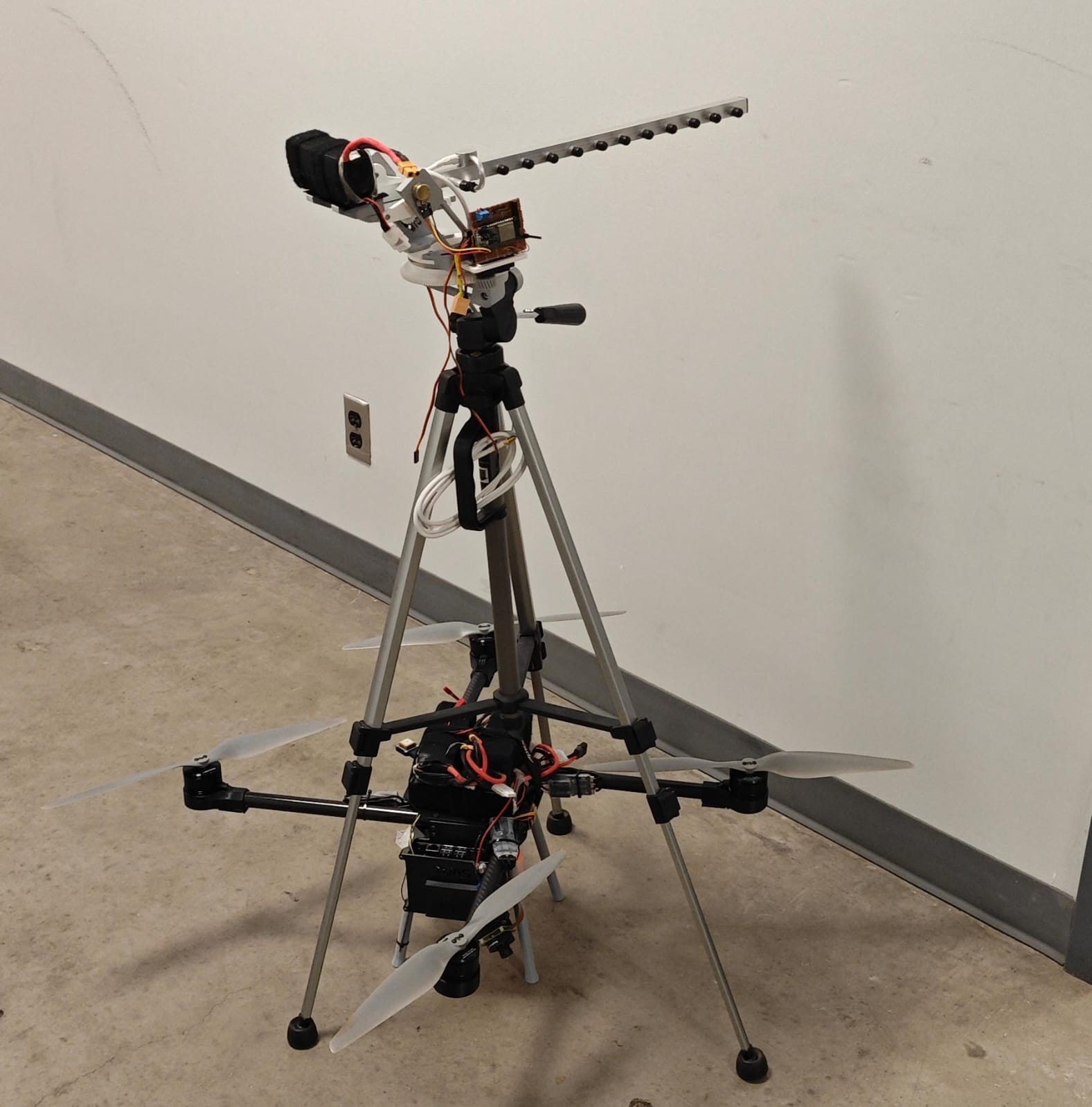
This project is an autonomous dual-axis antenna tracker designed to extend the operational range of long-distance drone missions. Its primary purpose is to maintain a strong, stable data link by continuously pointing a high-gain Yagi antenna directly at a moving aircraft.
A high-gain antenna like the Yagi sacrifices a wide field of view for a focused, long-range beam. Without tracking, the aircraft would quickly fly out of this narrow beam, causing a loss of telemetry and video. This system solves that problem by calculating the real-time bearing to the aircraft and physically adjusting the antenna’s orientation to maintain the optimal connection.
How it Works: The system receives the aircraft’s GPS coordinates via a WiFi UDP connection. Using its own GPS-determined location and heading from an onboard magnetometer, the tracker calculates the precise azimuth and elevation angles to the target. A PID control loop on an ESP32 microcontroller then commands modified servos to rotate the antenna and keep it pointed at the aircraft.
Technologies & Skills Demonstrated
- Embedded Systems & Firmware
- Developed real-time control firmware for an ESP32 Feather microcontroller, handling concurrent tasks: UDP packet parsing, sensor data acquisition, and PID loop execution.
- Integrated multiple I²C peripherals (QMC5883L magnetometer, GPS module) with robust error handling and data validation.
- Implemented efficient GPS data parsing using the TinyGPS++ library to extract and transform geodetic coordinates.
- Designed and tuned a custom PID control algorithm for actuator control, converting angular error into precise PWM signals.
- Wireless Communication & Networking
- Engineered a system utilizing a 2.4 GHz Yagi antenna for maximizing signal-to-noise ratio in long-range applications.
- Configured a local WiFi network and implemented a lightweight UDP protocol for low-latency transmission of telemetry data from a ground control station (GCS) to the tracker.
- Mechanical Design & Prototyping
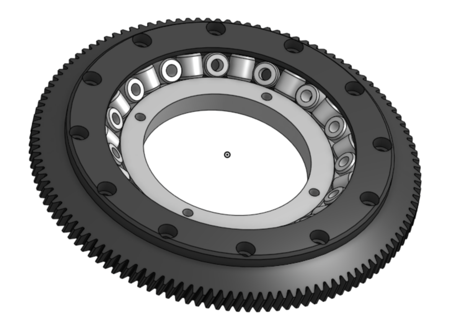
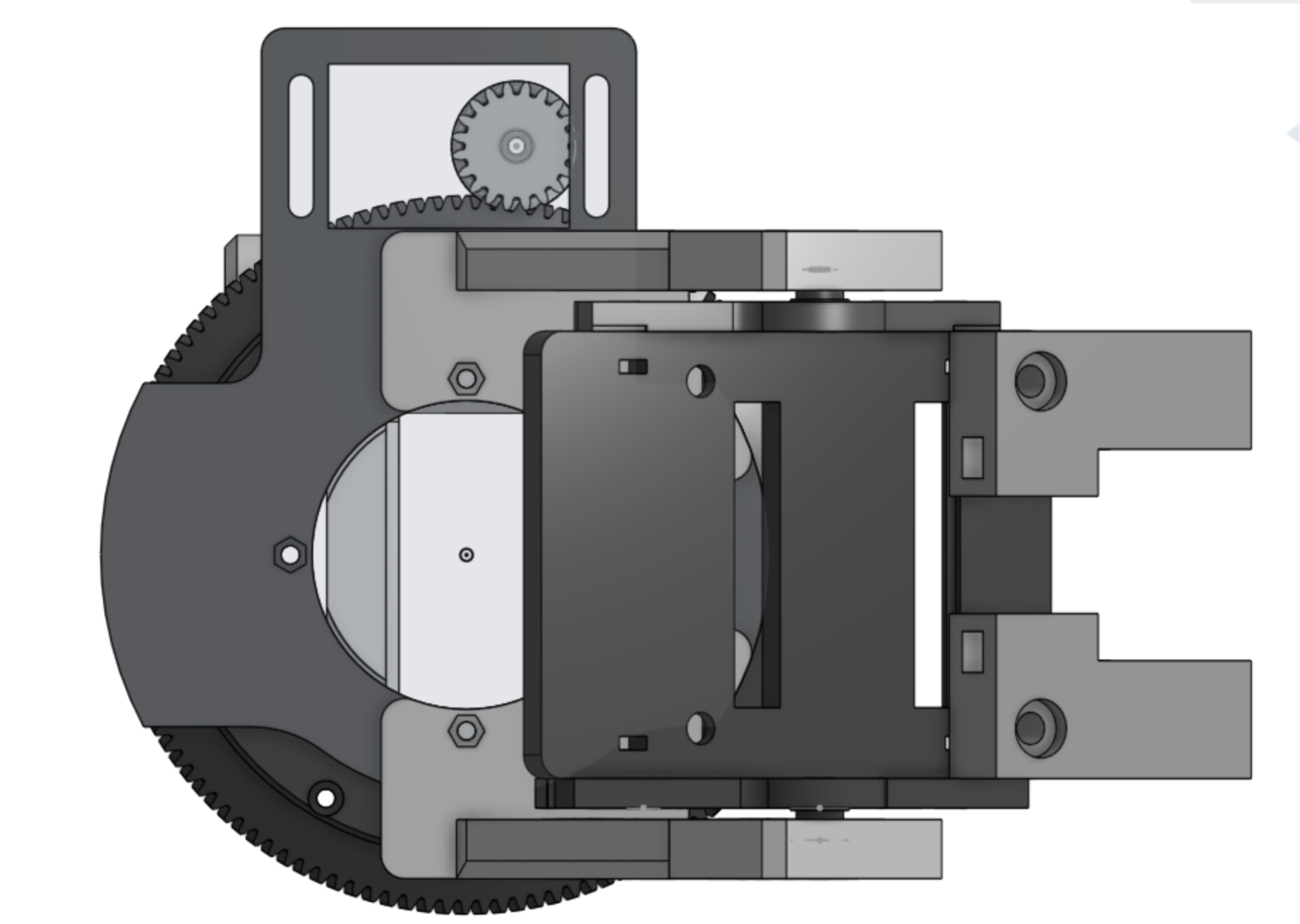
- Designed a structurally sound and functional assembly in Onshape CAD, featuring a custom 3D-printed thrust bearing for smooth 360° azimuth rotation.
- Modeled and fabricated bespoke components including servo mounts, a tripod attachment system with a friction lock, and an electronics enclosure.
- Data Processing & Algorithms (Python & C++)
- Developed a sensor calibration suite in Python utilizing ellipsoid fitting algorithms to characterize and compensate for hard and soft iron distortions in the magnetometer, significantly improving heading accuracy.
- Implemented the ECEF (Earth-Centered, Earth-Fixed) coordinate transformation to accurately calculate the bearing between two GPS coordinates on a spherical earth model.
- Electronics & Integration
- Assembled and integrated all electronic subsystems, including power regulation, sensor interfacing, and servo control.
- Modified standard hobby servos for continuous rotation, requiring careful soldering and mechanical alteration.
Project Development
CAD design


The first phase involved designing the entire mechanical system in Onshape CAD. Key design challenges and solutions included:
-
360° Rotation: A custom-designed, 3D-printed thrust bearing was created to provide smooth, continuous azimuth rotation without wiring entanglement.
-
Stability & Rigidity: A sturdy servo mount for elevation control and a reinforced base ensure minimal vibration and precise pointing.
-
Mounting System: A friction-based clamp mechanism was designed for secure and quick attachment to a standard camera tripod.
Mechanical Testing – 3D printed Bearing
Several iterations of the thrust bearing were printed to optimize tolerances. The final design, after adjusting roller size and clearance, achieved a smooth, low-friction rotation essential for accurate servo control.
180 -> 360 Servo modification
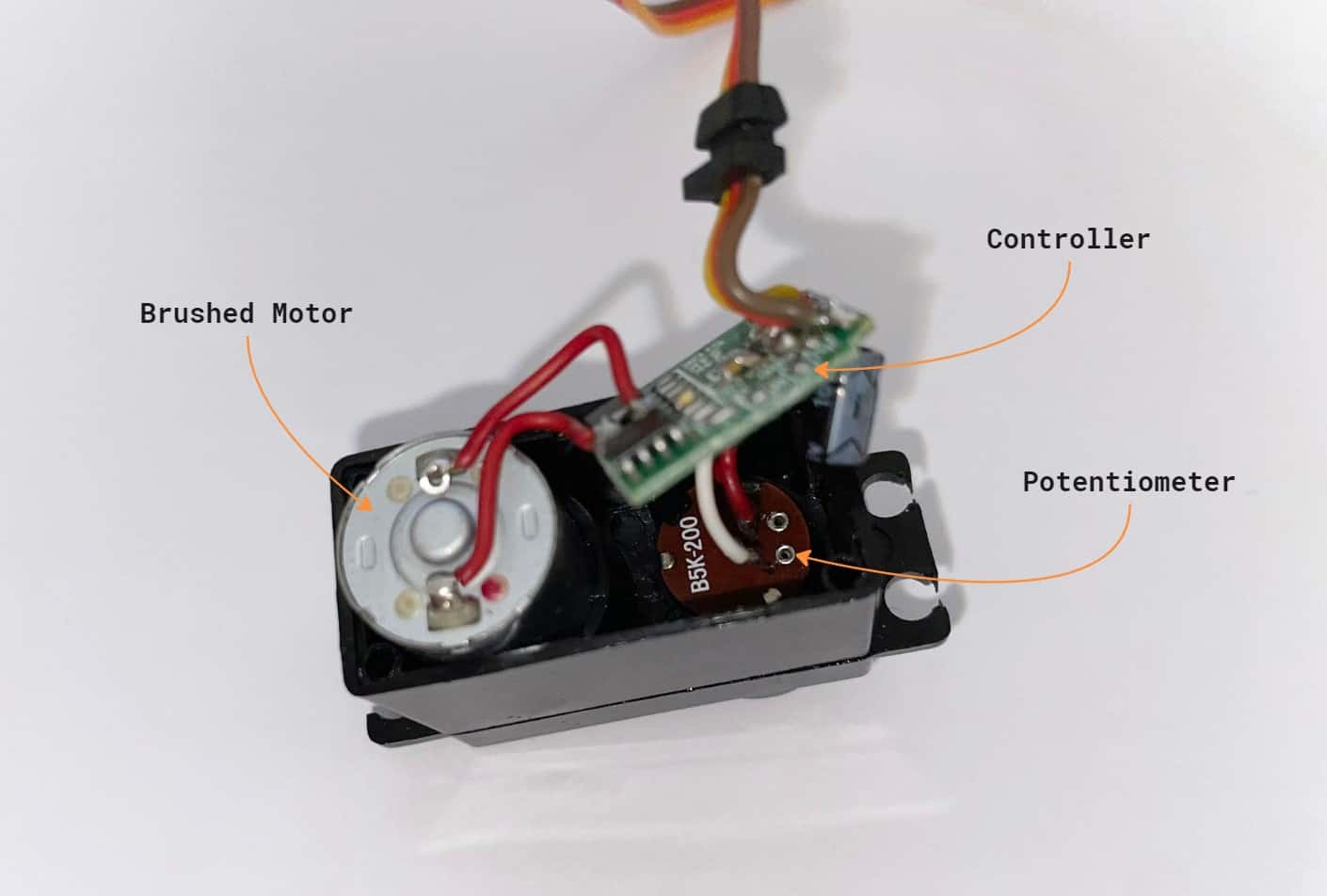
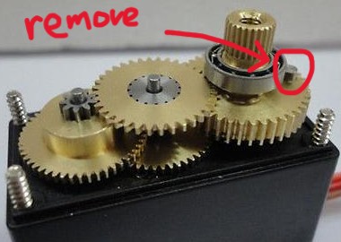
The azimuth axis requires full 360° rotation, which standard servos cannot provide. The solution was a hardware and software modification:
1) Hardware: The internal potentiometer was fixed at its center position, and the physical rotation limit stop was removed. This tricks the servo’s internal control board into continuously driving the motor.
2) Software: The modified servo now interprets a PWM signal as a velocity command rather than a position command. This necessitated the implementation of a custom PID controller on the ESP32 to read the actual position (from the magnetometer) and calculate the necessary velocity/direction to reach the target azimuth.
PID tuning and testing
The PID controller was initially tuned by setting a fixed angular setpoint and manually perturbing the system. This process involved:
-
Proportional (P) Gain: Adjusted for responsiveness without causing overshoot or oscillation (limited by the servo’s maximum physical speed).
-
Integral (I) Gain: There are no steady-state errors in this system thus this term is omitted.
-
Derivative (D) Gain: Added to dampen the system and reduce overshoot. This term was very low for this system since there is are mechanical damping from the friction of the 3D printed bearing.
Elliptical fit for soft & hard iron calibration
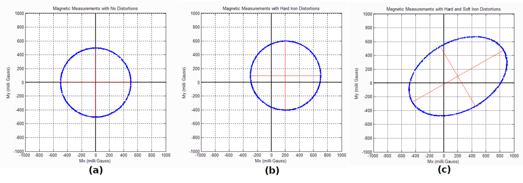
To maximize heading accuracy, a sophisticated calibration method was implemented to address sensor distortions:
-
Hard Iron Effects: Caused by permanent magnetic fields, resulting in a constant offset to all readings.
-
Soft Iron Effects: Caused by materials that distort but do not produce magnetic fields, resulting in a scaling and skewing of the magnetic field sphere into an ellipsoid.
A Python script was developed to perform an ellipsoid fit on data collected from rotating the magnetometer through all orientations. This algorithm calculates a transformation matrix and offset vector that maps the distorted ellipsoid of raw data back onto a centered sphere, correcting for both hard and soft iron errors simultaneously. This is a significant improvement over simple min/max calibration.
Integration Test: Virtual Aircraft
Before a live flight, the entire system was validated using a software-in-the-loop test. The open source flight control software, Ardupiolot, provides and API that simulated a moving aircraft, broadcasting its GPS coordinates via UDP over WiFi. This test verified the complete data pipeline: network communication, coordinate transformation, PID control logic, and physical actuation.
Live Test: Actual Aircraft
The system successfully tracked a quadcopter in flight, maintaining a strong data link at ranges where a static antenna would have failed. The tracker demonstrates smooth and accurate pointing behavior, confirming the effectiveness of the mechanical design, sensor calibration, and control algorithms.
Challenges + Solutions
The primary challenge throughout development was achieving consistent pointing accuracy. The initial performance was erratic, with significant tracking errors. A systematic, layer-by-layer approach was employed to isolate and resolve the contributing factors:
1) Problem Isolation: The control loop was broken down into discrete components:
- Input (Sensors): Aircraft GPS, Tracker GPS, Tracker Compass.
- Processing: ECEF Bearing Algorithm.
- Output: PID Controller & Servos. Each component was tested in isolation.
- ECEF Algorithm: Validated with known coordinate pairs from Google Maps. Verification: Passed.
- PID Controller: Tested with a fixed setpoint. Identification: Responsiveness was limited by the servo’s maximum speed, but it was functionally correct.
- Sensors: Identified as the main source of error.
2) Sensor Error Decomposition: The compass inaccuracy was further decomposed into systematic and random errors:
-
Systematic Errors:
-
Incorrect Orientation: Physical misalignment of the sensor on the PCB. Solution: Added a fixed angle offset in software.
-
Magnetic Declination: The difference between magnetic north and true north. Solution: Implemented a declination correction based on geographic location.
-
Hard/Soft Iron Distortions: Caused by the tracker’s own electronics and metal components. Solution: Developed the ellipsoid fitting calibration script.
-
Random Errors:
-
GPS Noise: Inherent jitter in the GPS positional data (~1-2m accuracy).
-
Solution Implementation: The systematic errors were addressed first. The ellipsoid calibration and declination correction resulted in a dramatic improvement in heading accuracy, which directly translated to precise tracking. The random errors were mitigated by tuning the PID loop to be aggressive enough to correct for drift but not so aggressive that it oscillated from sensor noise.
-
This methodical process of hypothesis, isolation, and validation was critical to diagnosing the complex, multi-variable problem. It transformed the project from a non-functional prototype into a reliable system.
Future Improvements
-
Sensor Fusion for Tilt Compensation: The current compass reading is only accurate when the tracker is level. Integrating an IMU (Inertial Measurement Unit) would allow for tilt compensation using accelerometer data. Implementing a Kalman Filter would fuse data from the compass, accelerometer, and gyroscope to provide a robust and accurate 3D orientation estimate, even on uneven ground.
-
True Continuous 360° Rotation: Replacing the long cable with a slip ring would eliminate the need to unwind the tracker, enabling truly unlimited azimuth rotation.
-
Extended Communication Protocol: Enhancing the UDP protocol to include more telemetry data (e.g., aircraft heading, altitude) could allow for predictive pointing and even more robust tracking.
-
Waterproof Enclosure & Ruggedization: Designing a weatherproof case would make the system suitable for prolonged outdoor use in various conditions.