Project demonstration
Project Overview
Timeline: January 22 2025 - April 25 2025 (~3 months)
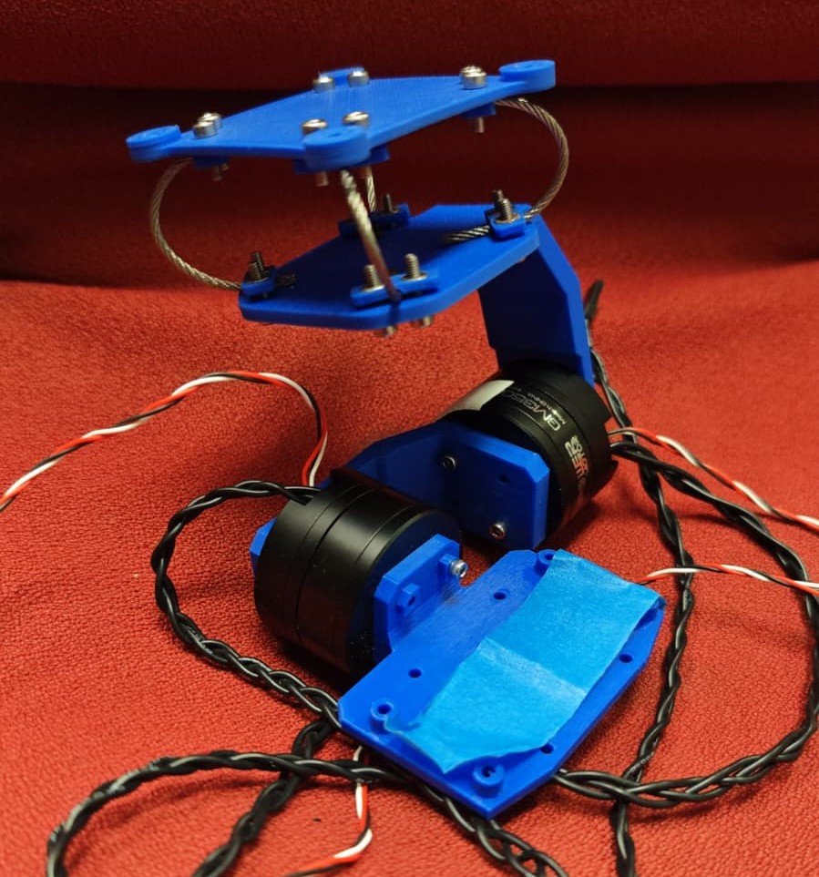
This project involved designing and implementing a complete camera gimbal system capable of maintaining camera stability during autonomous drone missions. The system provides critical stabilization for computer vision tasks, ensuring clear image capture essential for navigation, mapping, and object recognition algorithms.
The gimbal utilizes an IMU for attitude sensing, custom ESC firmware for precise motor control, and implements a sophisticated control pipeline: IMU data acquisition via I2C, error computation, PID control algorithms, torque calculation, and Field-Oriented Control (FOC) implementation with encoder feedback. Communication between the dual ESCs is handled through a custom CAN bus protocol, enabling coordinated 2-axis stabilization.
Technologies & Skills Demonstrated
- Mechanical Design
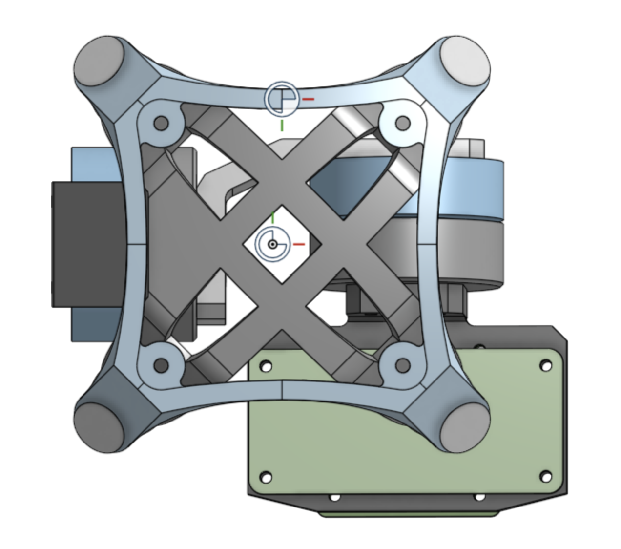
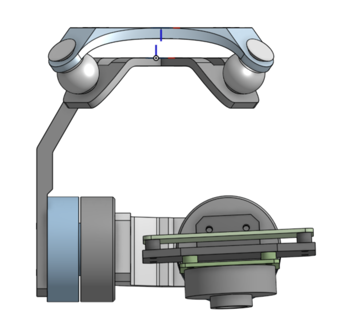
- CAD Engineering: Onshape design featuring vibration dampeners with steel cables, aircraft integration considerations, and optimized 2-axis cantilevered design to minimize high-frequency vibrations
- Prototyping: 3D printing, bearing selection, and mechanical assembly optimization
- Embedded Systems & Firmware
- Microcontroller: STM32G431CBU6 ESC development
- Communication Protocols: I2C (MPU6050 IMU), CAN bus (inter-ESC communication), UART (debugging)
- Motor Control: Closed-loop FOC implementation with magnetic encoder feedback
- Control Theory: PID tuning, inverse Park and Clarke transformations, real-time control algorithms
- Electronics & Hardware
- PCB Design: Schematic reading, board assembly, and troubleshooting
- Soldering: Surface-mount and through-hole component assembly
- System Integration: Sensor integration, power management, and noise reduction
Project Development
Mechanical Design & CAD
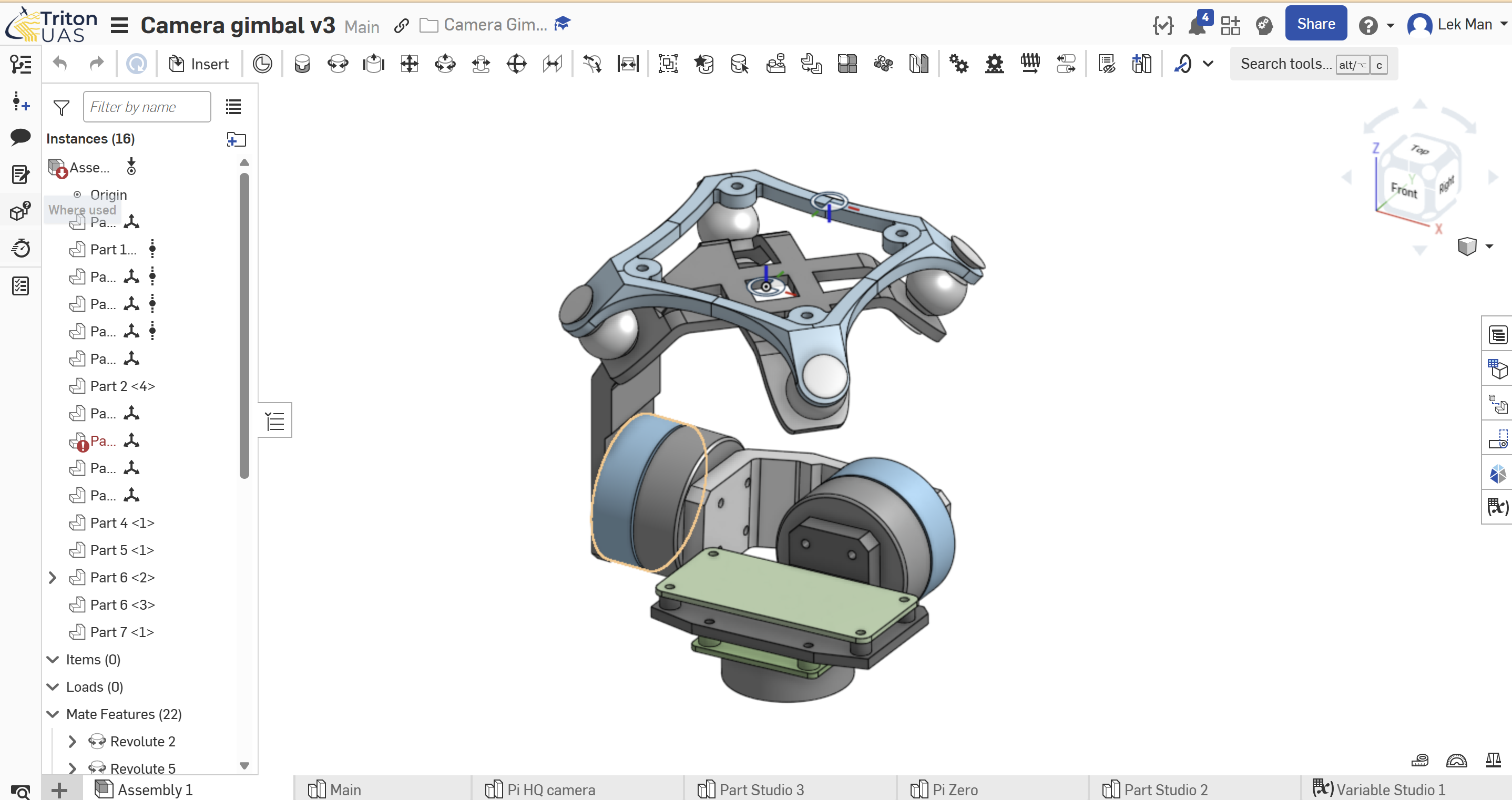

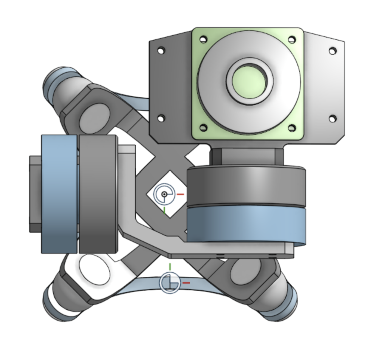
The mechanical design phase focused on creating a robust yet lightweight system capable of handling aerial vibrations while maintaining precise camera positioning. Key design considerations included:
- Vibration Isolation: Implemented steel cable damping system to decouple high-frequency vibrations from the drone airframe
- Cantilevered Axis Design: Optimized geometry to minimize moment arms and reduce resonance effects
- Weight Distribution: Balanced component placement to minimize power consumption and improve response characteristics
- Aircraft Integration: Designed mounting system compatible with standard drone frames while maintaining accessibility for maintenance
Field-Oriented-control implementation
The core of the motor control system involved implementing sensorless FOC to achieve smooth, precise BLDC motor operation:
// FOC control loop implementation
void BLDC_TorquetoPWM(float theta){

	float x;
	float y;

	//convert from electrical angle to mechanical angle
	theta = theta * POLE_PAIRS - EAU;
	//Inverse park transform
	x = d*cosf(theta) - torque*sinf(theta);
	y = d*sinf(theta) + torque*cosf(theta);

	//Inverse clarke transform
	a = x;
	b = -1.0*x/2.0 + y*M_SQRT3_OVER_2;
	c = -1.0*x/2.0 - y*M_SQRT3_OVER_2;

	counter_period = __HAL_TIM_GET_AUTORELOAD(&htim1);

	TIM1->CCR1 = ((a/2)+0.5)* counter_period;
	TIM1->CCR2 = ((b/2)+0.5)* counter_period;
	TIM1->CCR3 = ((c/2)+0.5)* counter_period;

//	sprintf(buffer, "%lu, %lu, %lu\r\n", TIM1->CCR1, TIM1->CCR2, TIM1->CCR3);
//	print(buffer);
}
The FOC implementation successfully demonstrated closed-loop encoder feedback, with the system generating proper 3-phase sine waves and maintaining torque control under external disturbances. The magnetic encoder provided accurate position feedback, enabling precise rotor position tracking essential for effective field orientation.
Taking this step futher, the motor is hooked up to power and the troque commands are converted, via the inverse Parke and Clarke transfroms, into PWM volatges across the 3 phases to spin the motor:
Side project (Playing music with a motor!)
After implementing FOC on the BLDC motor, I went off a slight tangent, building upon the previous FOC implementation to play music on the brushless DC motor.
See details of this side project
PID tuning and testing
The PID controller was systematically tuned to achieve optimal stabilization performance:
-
Proportional Gain: Balanced responsiveness with stability, limited by the physical constraints of motor maximum speed and acceleration
-
Integral Term: Omitted due to the absence of steady-state errors in this orientation control application
-
Derivative Gain: Carefully adjusted to provide damping without introducing high-frequency noise amplification
The tuning process involved setting fixed angular setpoints and analyzing the system’s response to manual perturbations, followed by iterative refinement based on step response characteristics.
A video of a sucessful PID posiiton control with the PID posiiton setpoint controlled by a poentiometer:
Integration Test: 1-axis
Initial integration testing validated the complete control pipeline from IMU reading to motor response:
The system demonstrated effective gimbal behavior, with the motor compensating for base movements to maintain the IMU (acting as camera proxy) in a stable orientation. This validation confirmed the proper integration of sensor acquisition, control algorithm computation, and motor actuation.
Integration Test: 2-axis with custom CAN communicatin
The final integration phase involved implementing custom CAN bus protocol for communication between the pitch and roll axis controllers:
// CAN message structure for inter-ESC communication
typedef struct {
    float imu_roll_angle;
    float imu_pitch_angle;
    float roll_axis_torque;
    float pitch_axis_torque;
    uint16_t checksum;
} gimbal_can_message_t;```
This distributed architecture allowed each ESC to run independent PID loops while sharing essential sensor data, creating a coordinated 2-axis stabilization system without requiring a central controller.
Challenges + Solutions
CAN Bus Communication Issues
Challenge: Spent approximately 7 hours troubleshooting CAN bus communication failures between the two STM32 controllers. Initial debugging focused on software configuration parameters within STM32CubeIDE, including baud rate settings, filter configurations, and interrupt priorities.
Root Cause Analysis: The issue was ultimately traced to a missing 120Ω termination resistor at the end of the CAN bus line, causing signal reflections that prevented reliable communication.
Solution: Added proper termination resistors and implemented a checksum verification system in the CAN message protocol to detect transmission errors. This experience reinforced the importance of systematic hardware troubleshooting before deep-diving into software issues.
Mechanical Resonance Damping
Challenge: Initial testing revealed high-frequency vibrations propagating through the gimbal structure, interfering with IMU readings and causing control instability.
Solution: Implemented a multi-stage damping approach combining steel cable isolation with strategic placement of damping material. Additionally, added software low-pass filtering to the IMU data to reject high-frequency noise without compromising control bandwidth.
FOC Implementation Complexity
Challenge:T he mathematical complexity of Field-Oriented Control presented implementation hurdles, particularly in managing the coordinate transformations and ensuring proper rotor angle estimation.
Solution: Developed a phased implementation approach, starting with open-loop sinusoidal drive validation, then incremental addition of encoder feedback, and finally full closed-loop torque control. Extensive use of debugging tools including logic analyzer and DAC-based waveform monitoring facilitated rapid iteration and validation.
Side project (playing music on a motor)
(Please turn on volume for the video to hear the music)
Building upon the FOC implementation, I developed a side project demonstrating audio synthesis capabilities of brushless motors. The system modulates torque setpoints at audio frequencies, effectively using the motor as a speaker.
Technical Implementation:
-
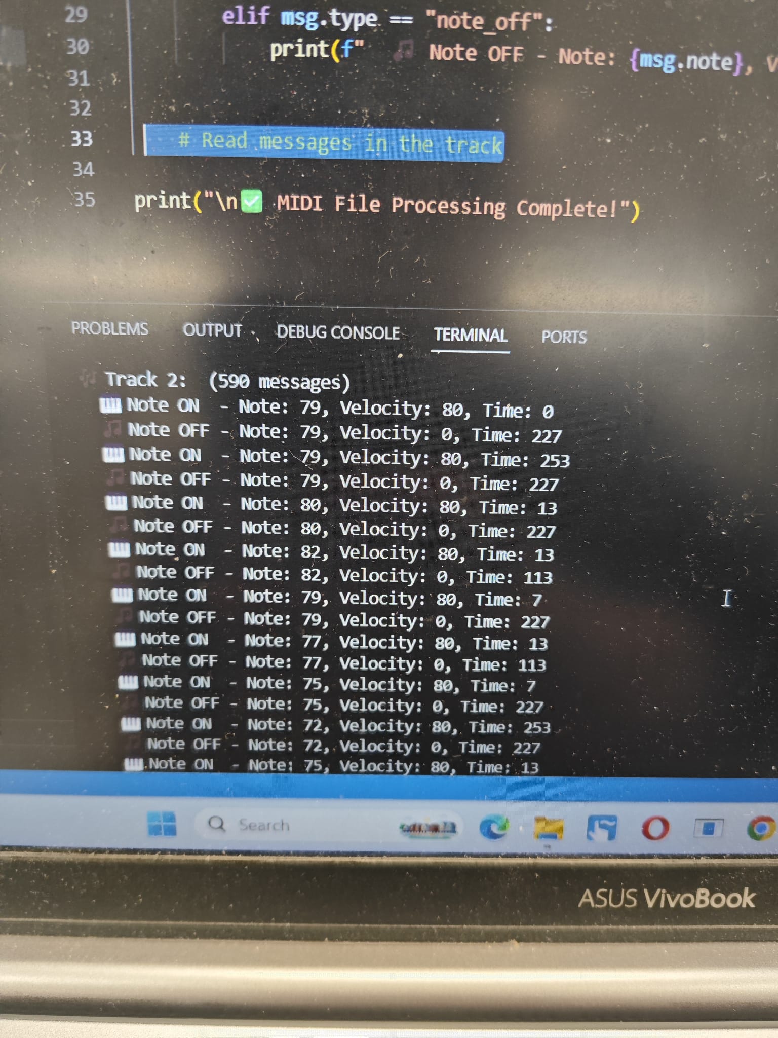
Created Python MIDI parser converting musical notes to corresponding frequency torque modulations
-
Implemented UART communication protocol for real-time audio streaming to the ESC
Video of the motor playing the music scale (please turn on volume):
This project showcased the versatility of the FOC implementation and provided valuable insights into high-frequency motor control limitations and resonant characteristics.
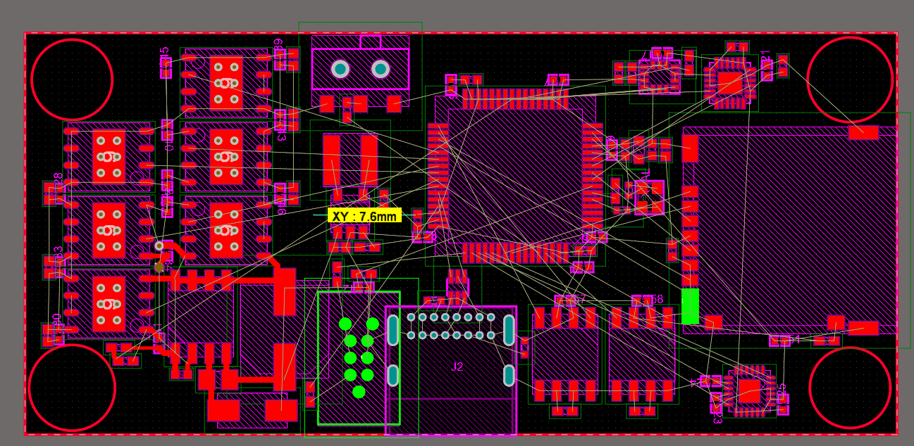
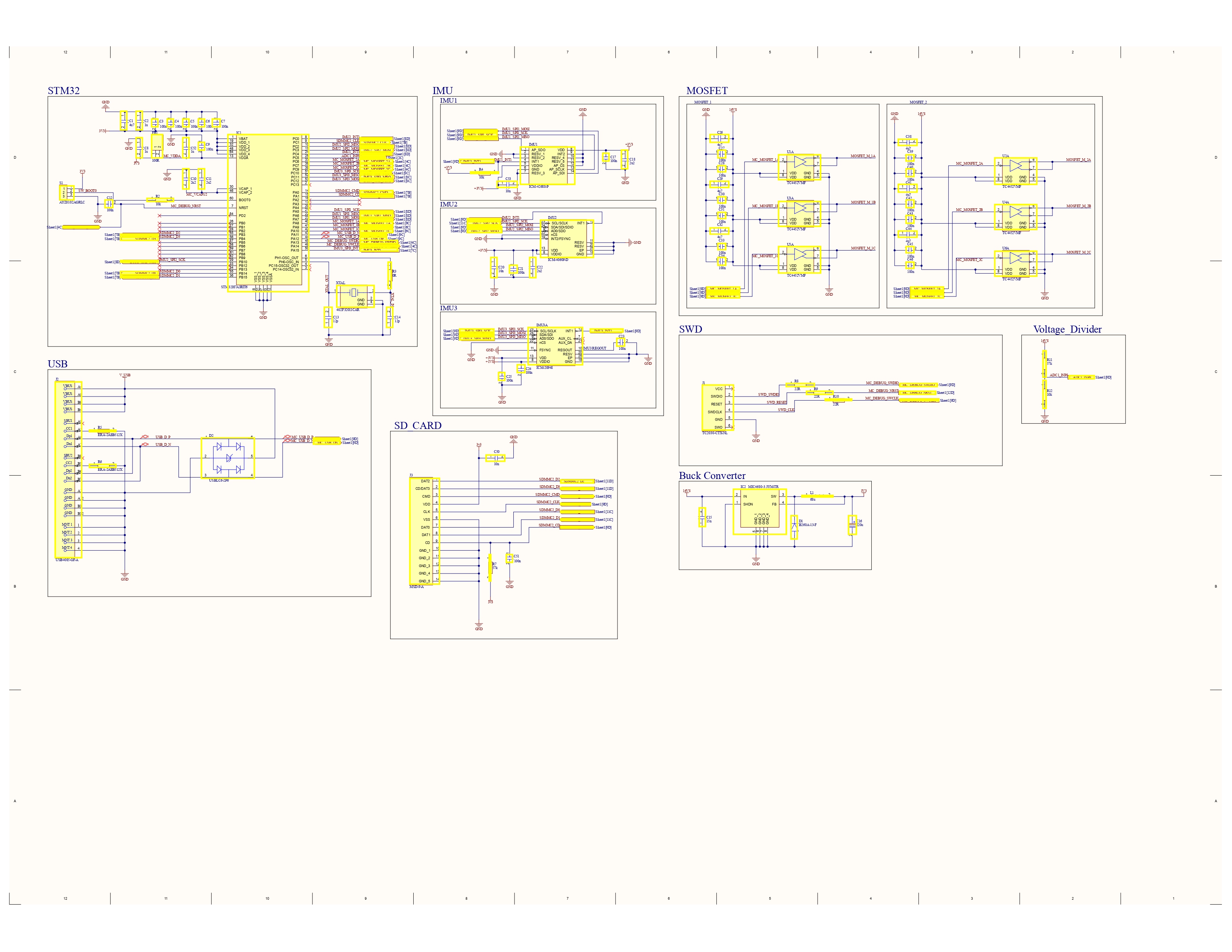
Customm ESC PCB (Work in progress)
Collaborating with team members to develop a custom PCB solution optimizing the gimbal control system:
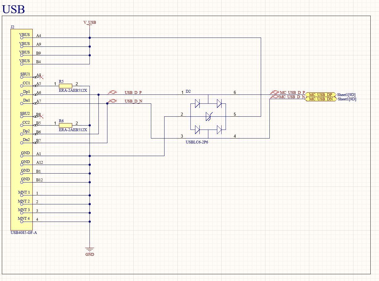
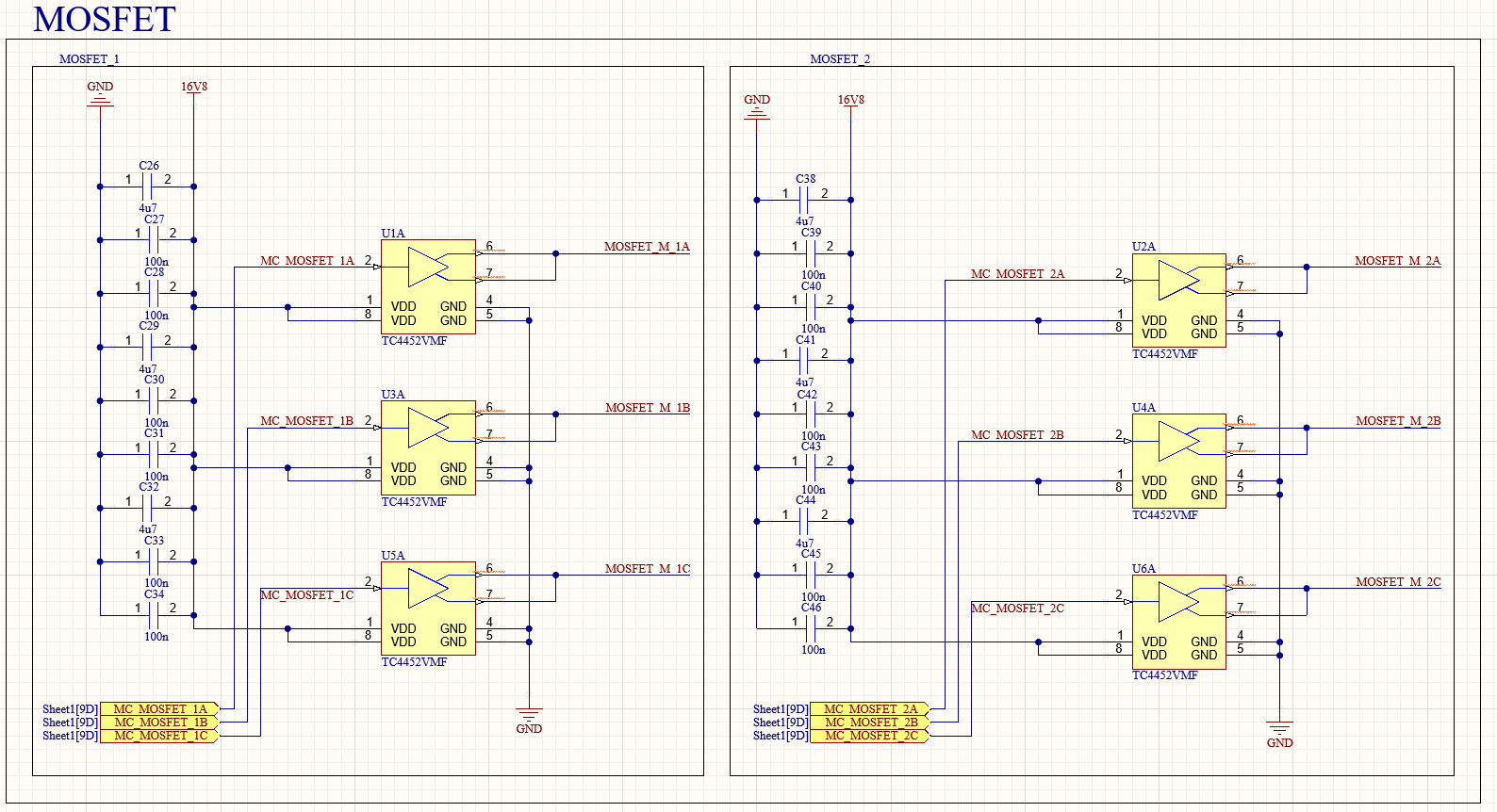
PCB Schematics, Layout & Traces:
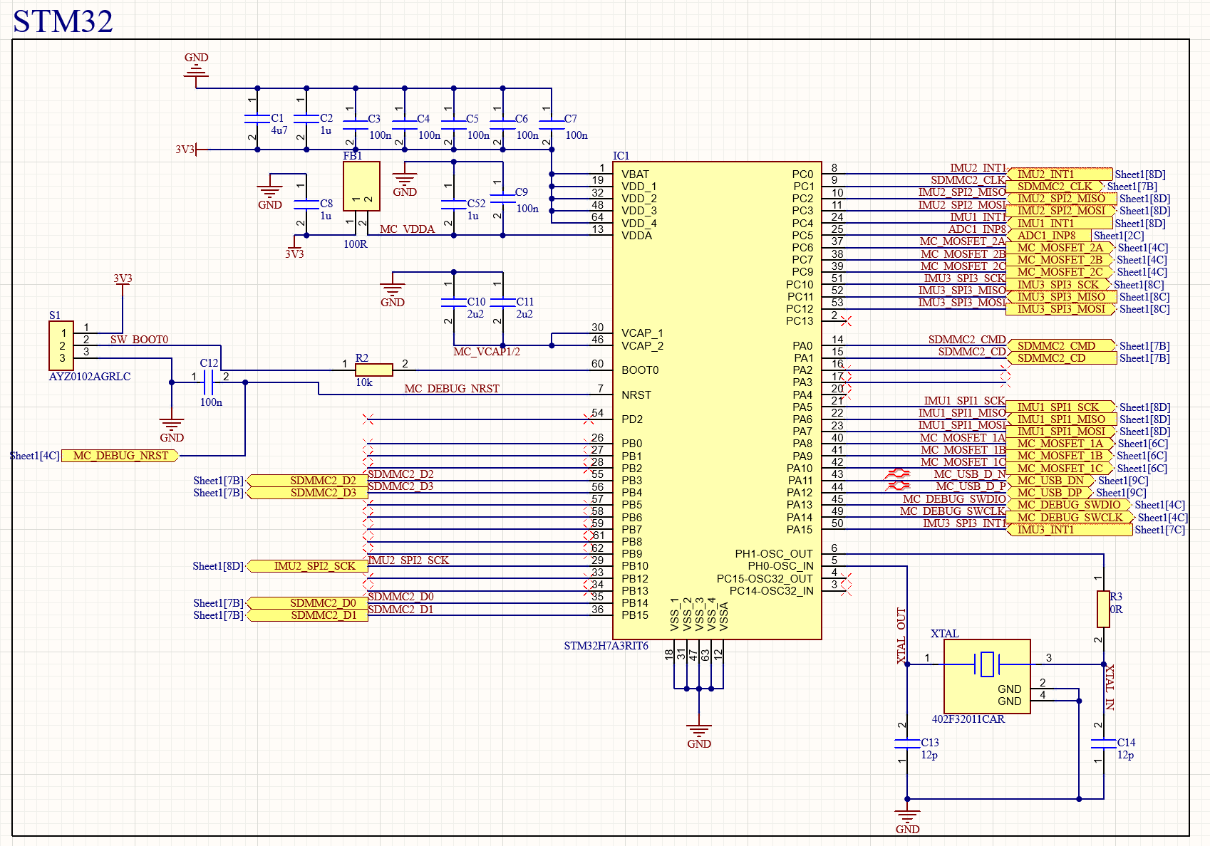
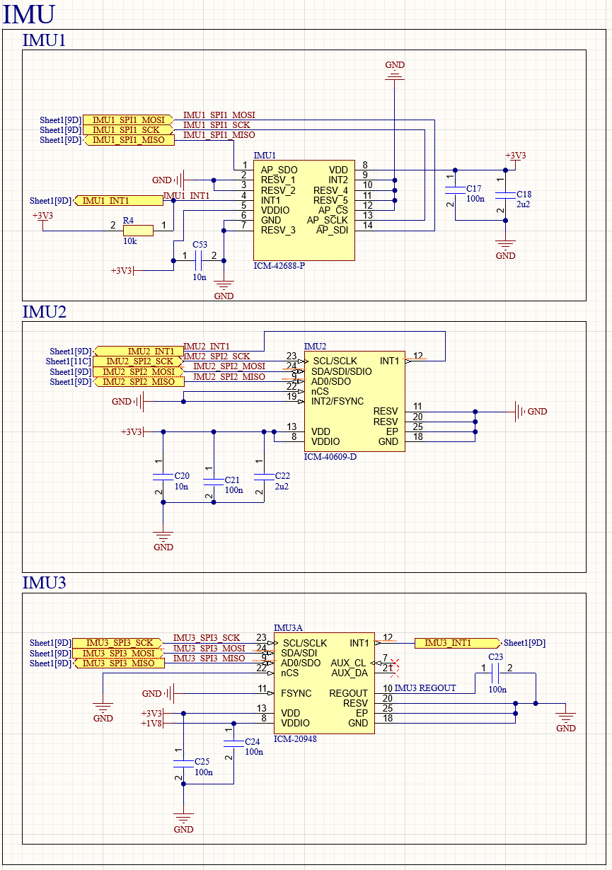
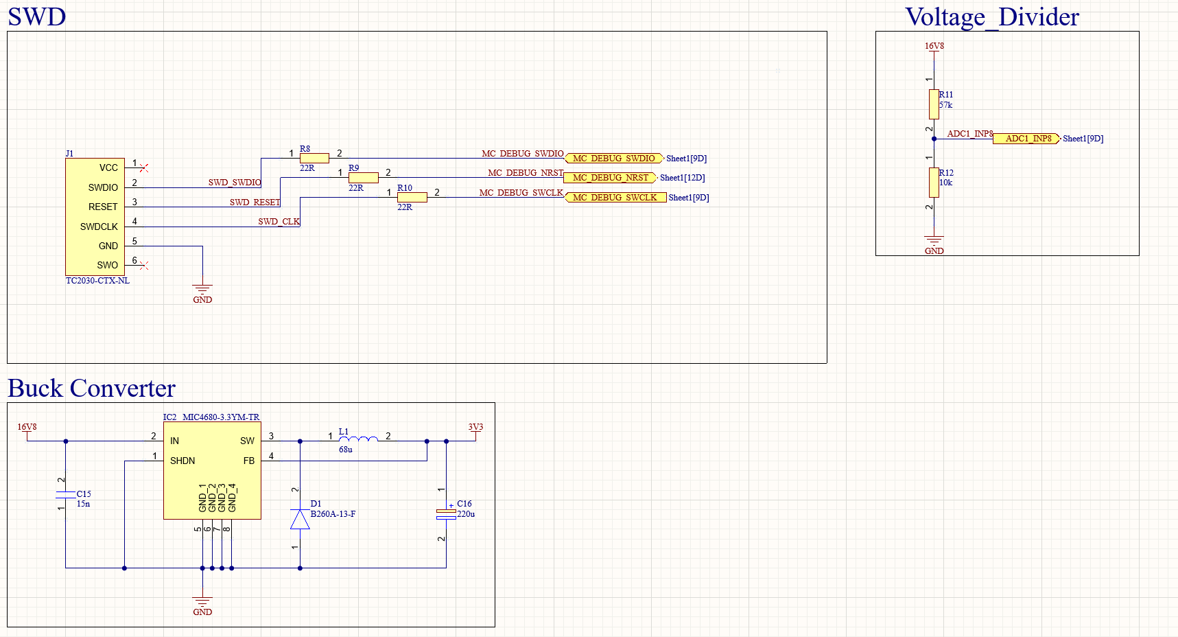
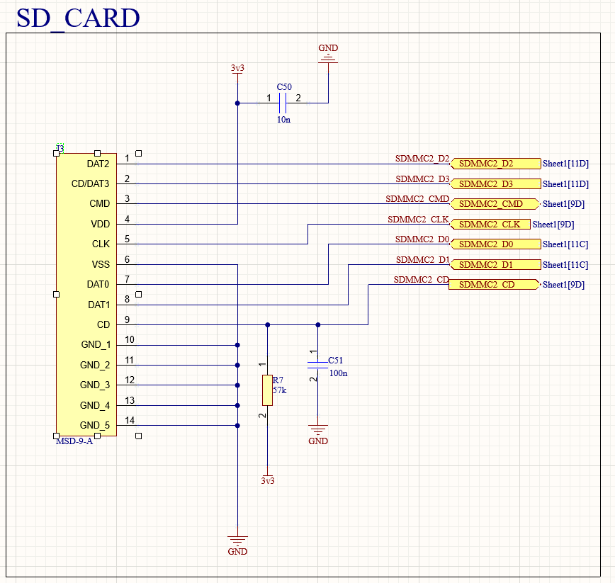
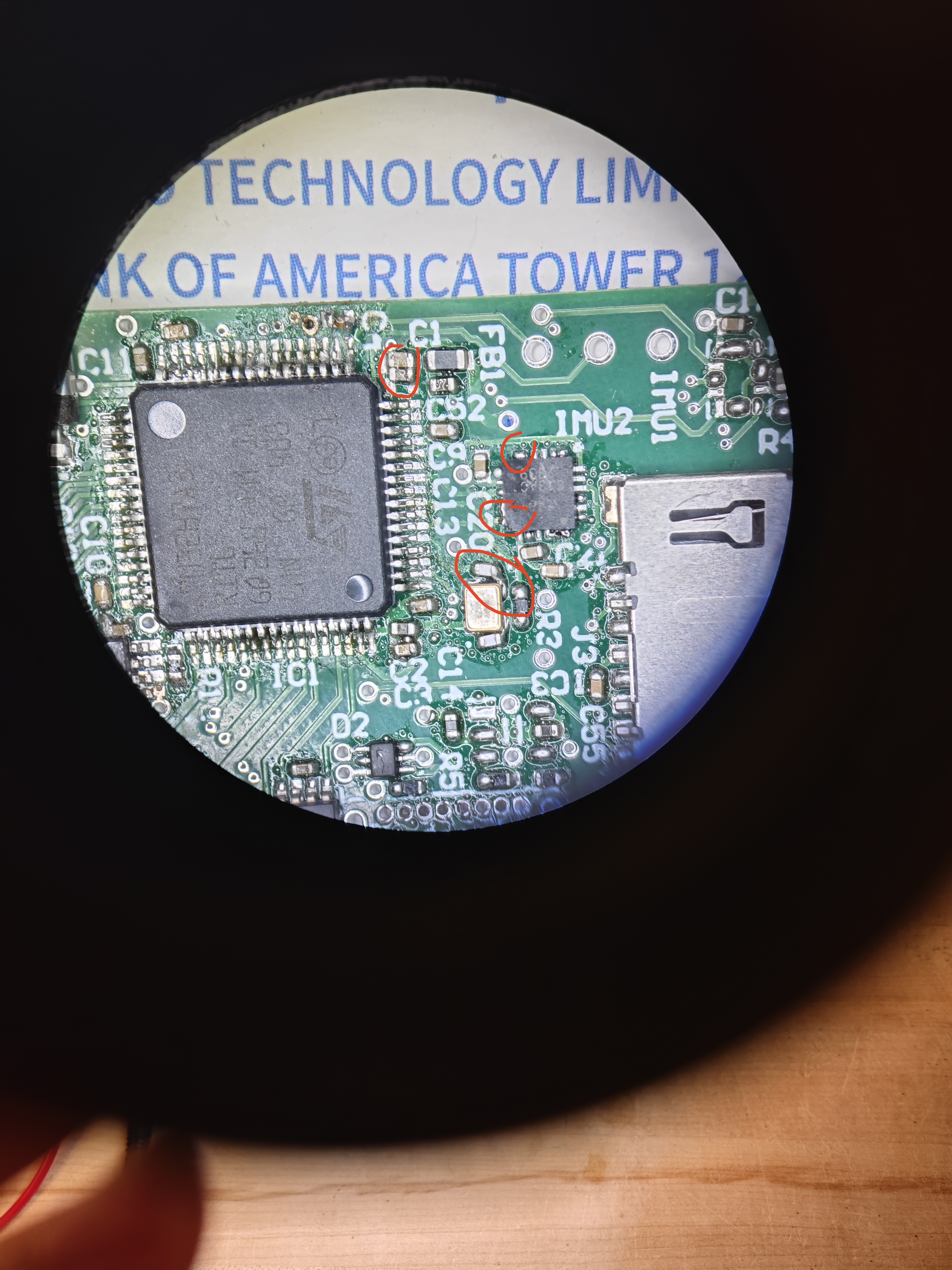
Assembly & Surface Mount Soldering:
Assemebled, soldered PCB:
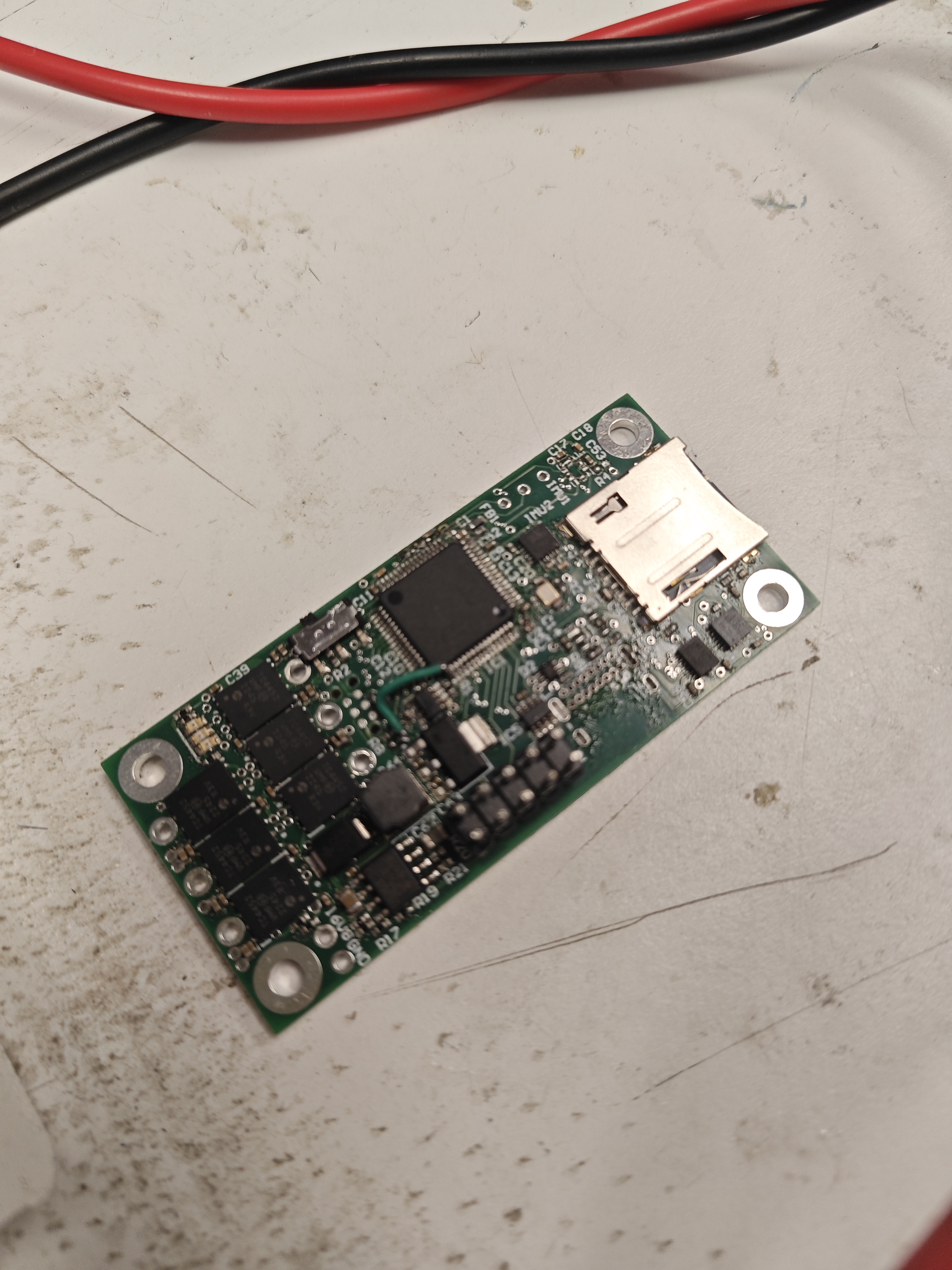
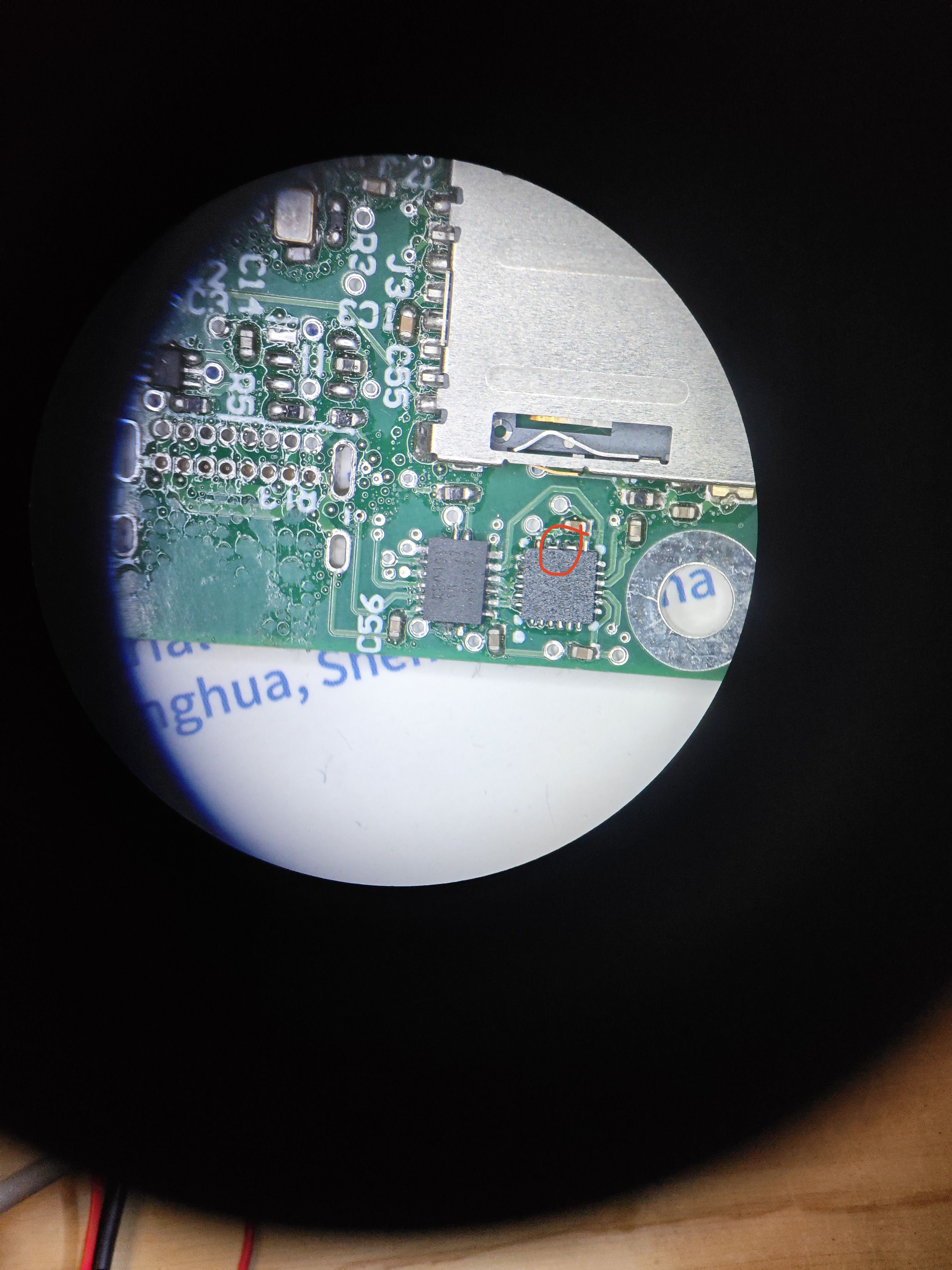
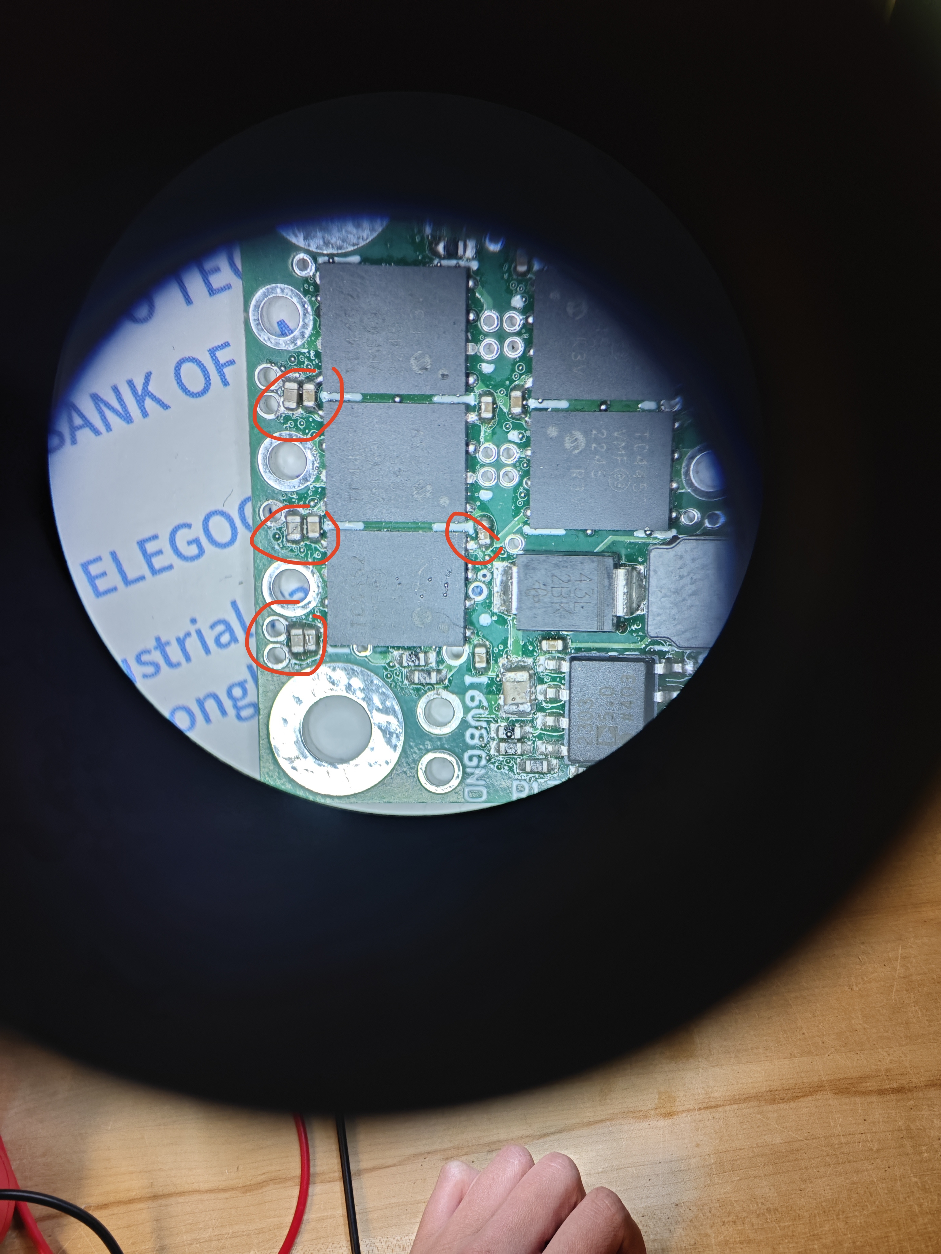
First successful Blink Sketch on custom gimbal board!!
The custom PCB integrates motor drivers, STM32 microcontroller, and all necessary interfaces into a compact form factor optimized for aerial applications, reducing weight and improving reliability compared to the prototype breadboard implementation.
Future Improvements
Enhanced Sensor Fusion
- Optimize complementary filter tuning to reduce drift.
- Integrate Pixhawk flight controller IMU data for improved stabilization accuracy.
- Develop quaternion-based orientation representation to eliminate gimbal lock issues.
Control Algorithm Advancements
- Implement adaptive PID tuning for varying payload conditions.
- Add feedforward control leveraging aircraft acceleration data.
- Develop model predictive control for improved disturbance rejection.
Hardware Refinements
- Complete development of the custom gimbal controller board.
- Optimize wire management and connector selection for reliability.
- Implement thermal management solutions for extended operation.
Software Infrastructure
- Create a configuration and tuning interface via ground station software.
- Implement data logging capabilities for performance analysis.
- Add safety features including failsafe modes and health monitoring.
This project demonstrates comprehensive skills in mechatronics system design—from mechanical CAD through embedded firmware development to advanced control system implementation—highlighting my ability to deliver complete engineering solutions for complex real-world problems.