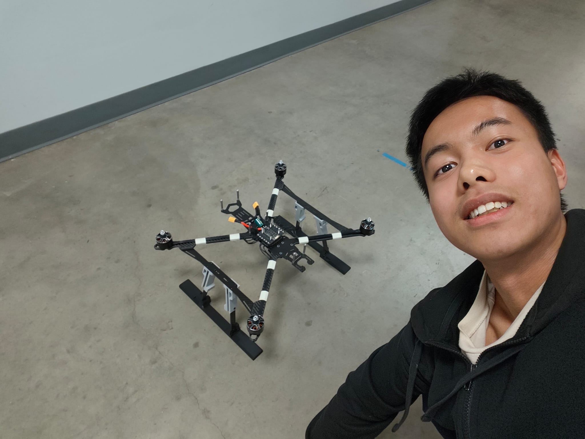
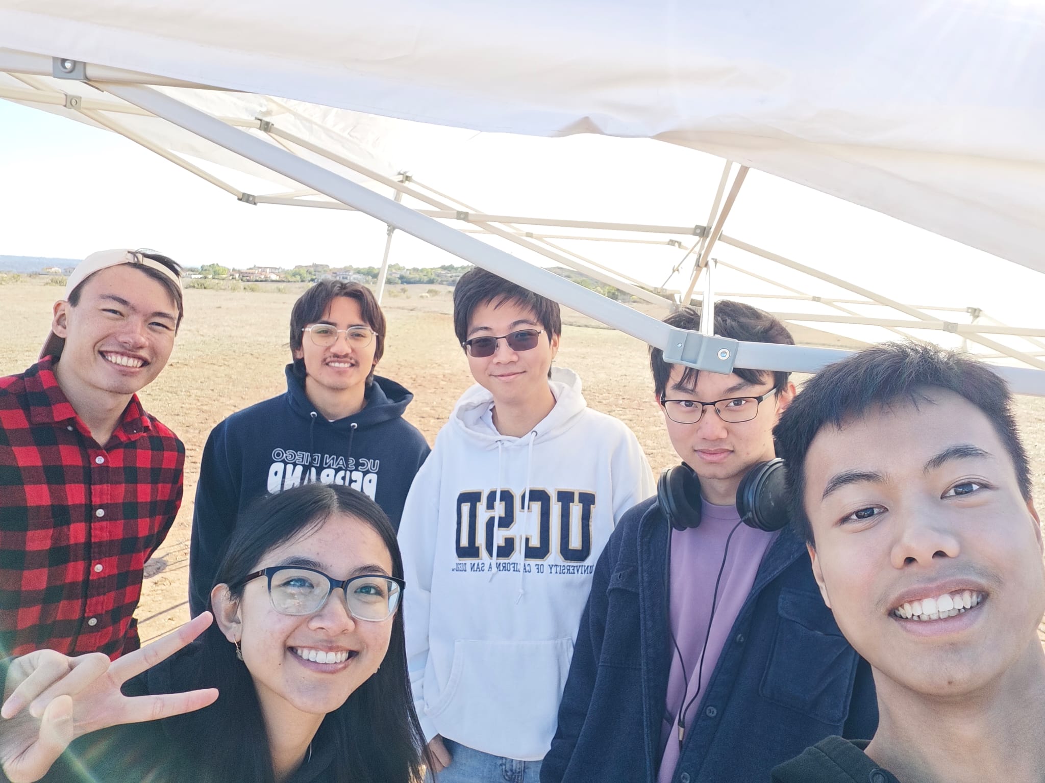
Final project demonstration
Project Overview
Timeline: June 2025 - February 27, 2026 (ongoing)
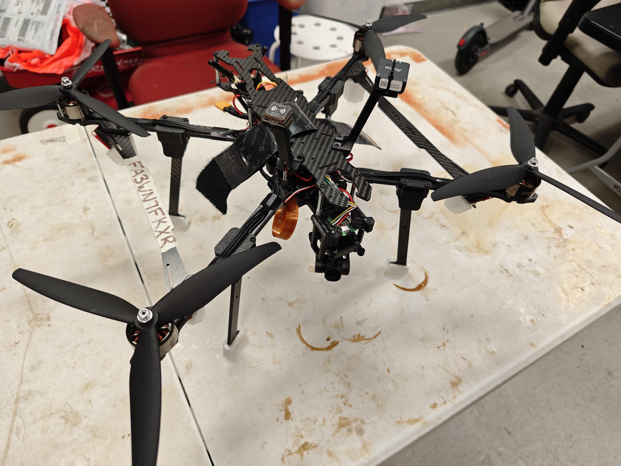
This project is a full ground-up design and integration of a 10-inch autonomous quadcopter for stable long-range flight and autonomous mission execution. I designed the mechanical platform in Onshape, sourced custom carbon-fiber manufacturing, built and soldered the complete powertrain/electronics stack, and tuned ArduPilot from first hover to guided autonomous operation.
Technologies & Skills Demonstrated
- Airframe and Mechanical CAD
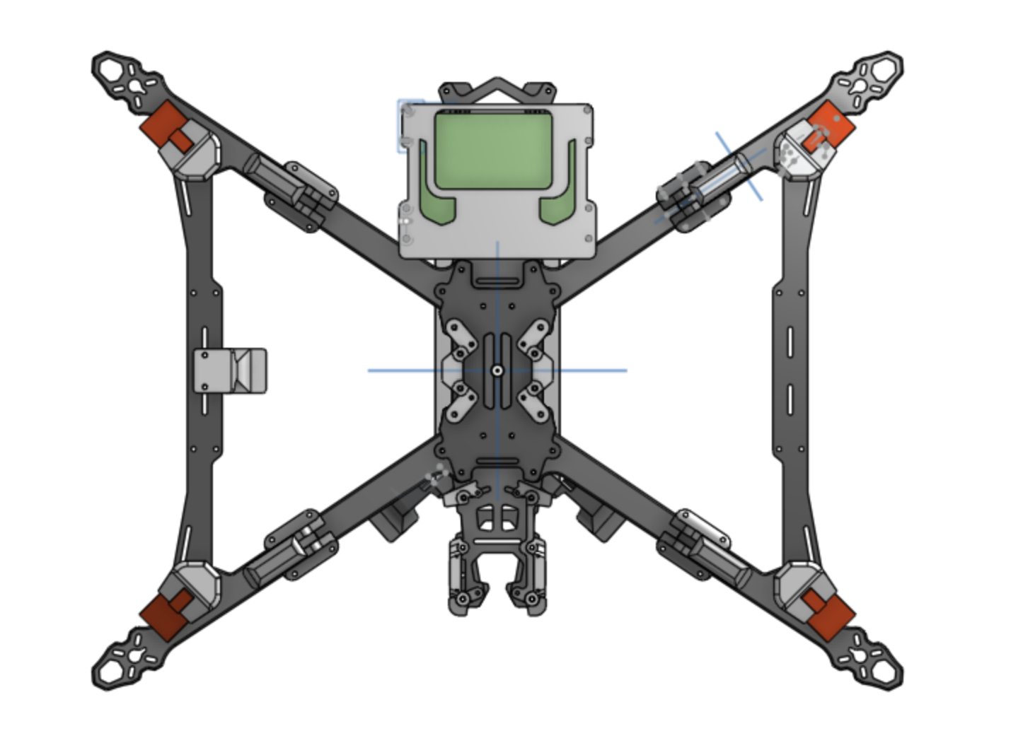
- Designed the complete frame architecture and custom parts in Onshape.
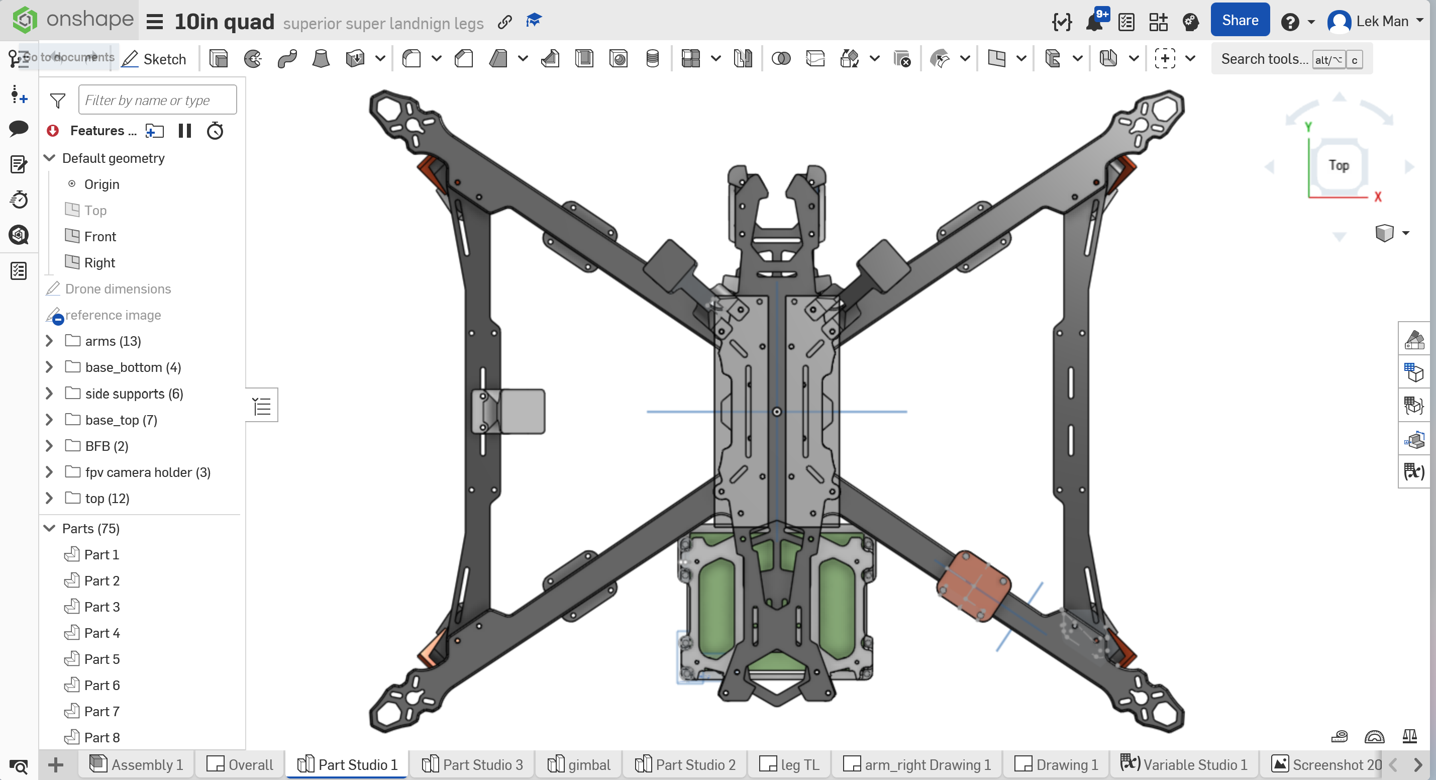
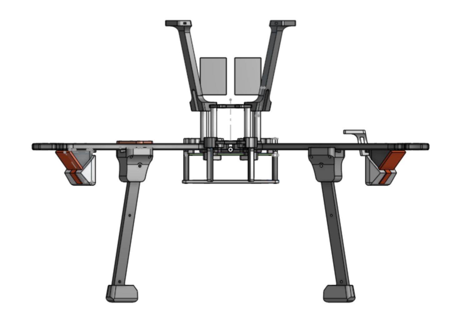
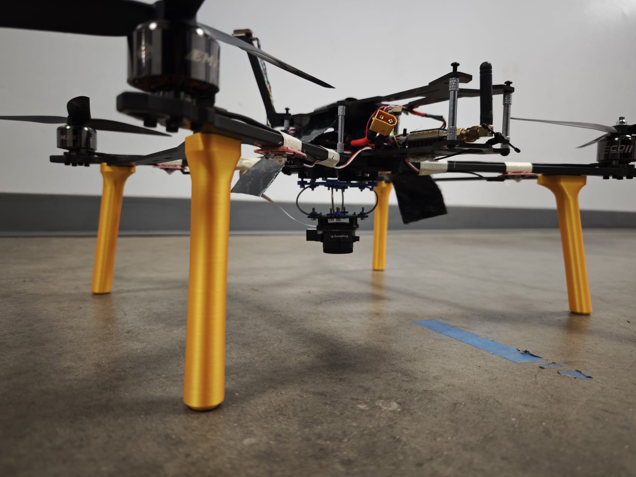
- Designed landing gear, gimbal mount, and Jetson mount with manufacturable geometry.
- Coordinated carbon-fiber manufacturing and validated tolerances during assembly.
- Powertrain and Electronics Integration
- Designed an 8S setup using two 4S packs in series based on mission power requirements.
- Selected motors, ESCs, GPS, radio, sensors, and power electronics for a stable autonomous stack.
- Performed full electrical integration, harnessing, and soldering.
- Flight Control and Autonomy
- Configured ArduPilot parameters from scratch for this platform.
- Performed iterative PID tuning for stability and handling.
- Progressed from manual test flights to stable loiter and guided autonomous takeoff.
- Testing and Debugging
- Conducted multiple test-flight campaigns and logged failure modes.
- Diagnosed and mitigated EKF variance events tied to electromagnetic interference.
- Iterated hardware layout and tuning to improve reliability.
Project Development
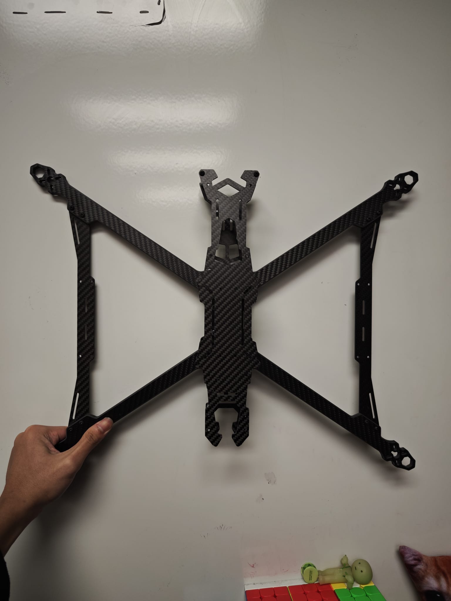
Mechanical design and CAD
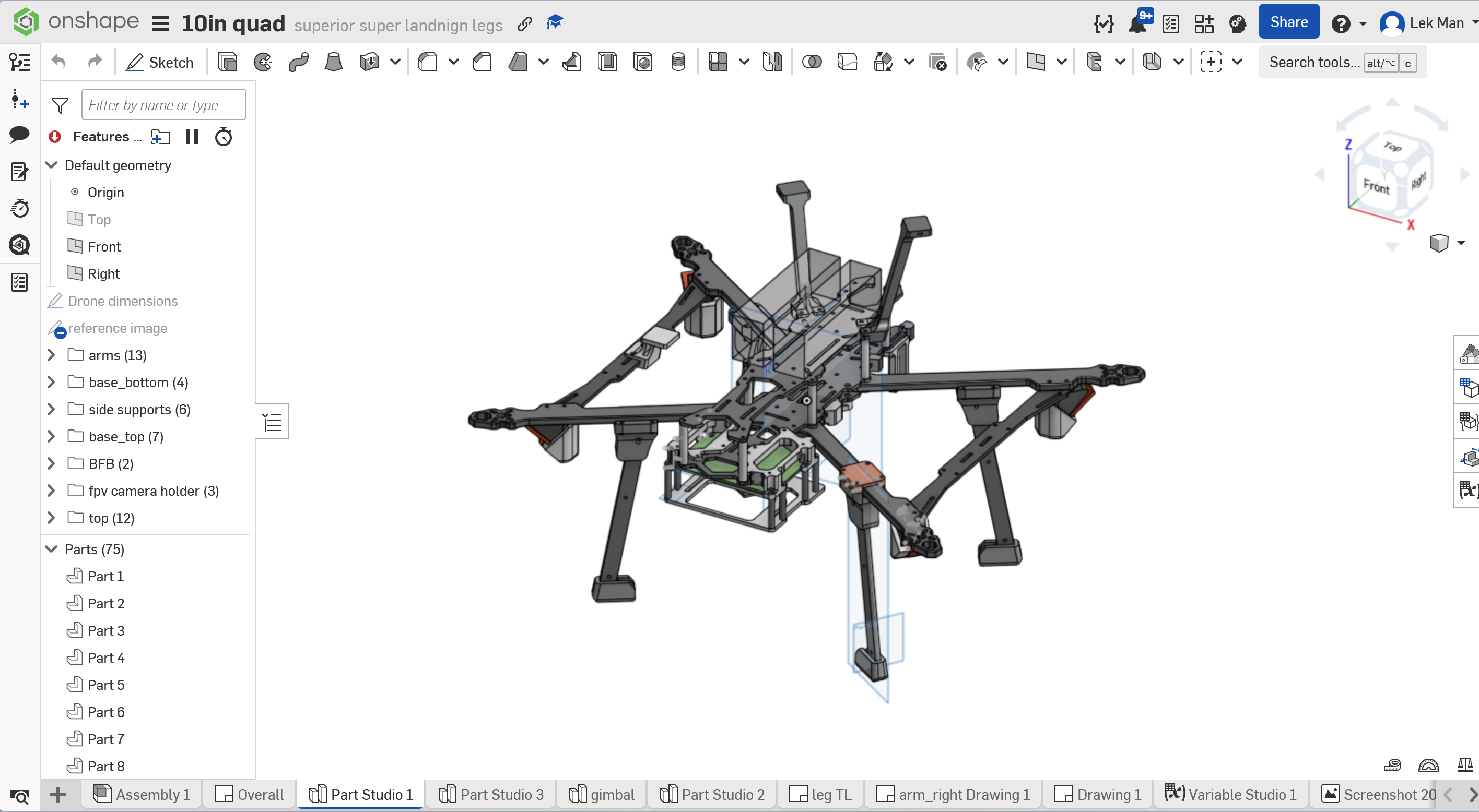
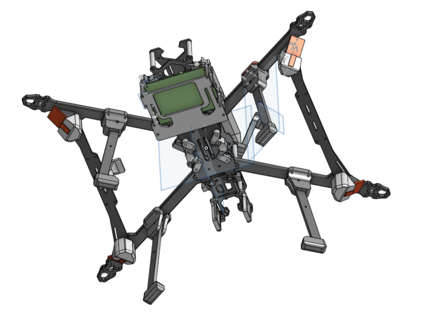
The development process began by defining mission constraints and translating them into CAD requirements: stiffness under thrust loads, clean packaging for avionics, maintainability, and growth room for autonomous payload/computing.
Design priorities:
- Frame stiffness and vibration behavior: geometry was tuned to reduce flex and vibration coupling into navigation sensors.
- Integration-friendly layout: mount locations were planned for power stack, GPS/radio, and future payloads.
- Serviceability: I avoided trapped fasteners and inaccessible interfaces so field fixes were practical.
Landing leg iterations
I treated landing gear as a separate mini-project because real-world handling quickly exposed weaknesses that CAD alone did not fully predict.
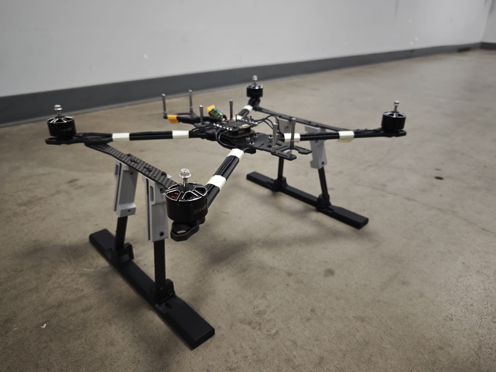
Iteration path:
- Version 1: validated attachment concept and geometry.
- Version 2: improved stance and impact behavior during repeated test sessions.
- Later revisions: improved durability and practical field handling while keeping weight reasonable.
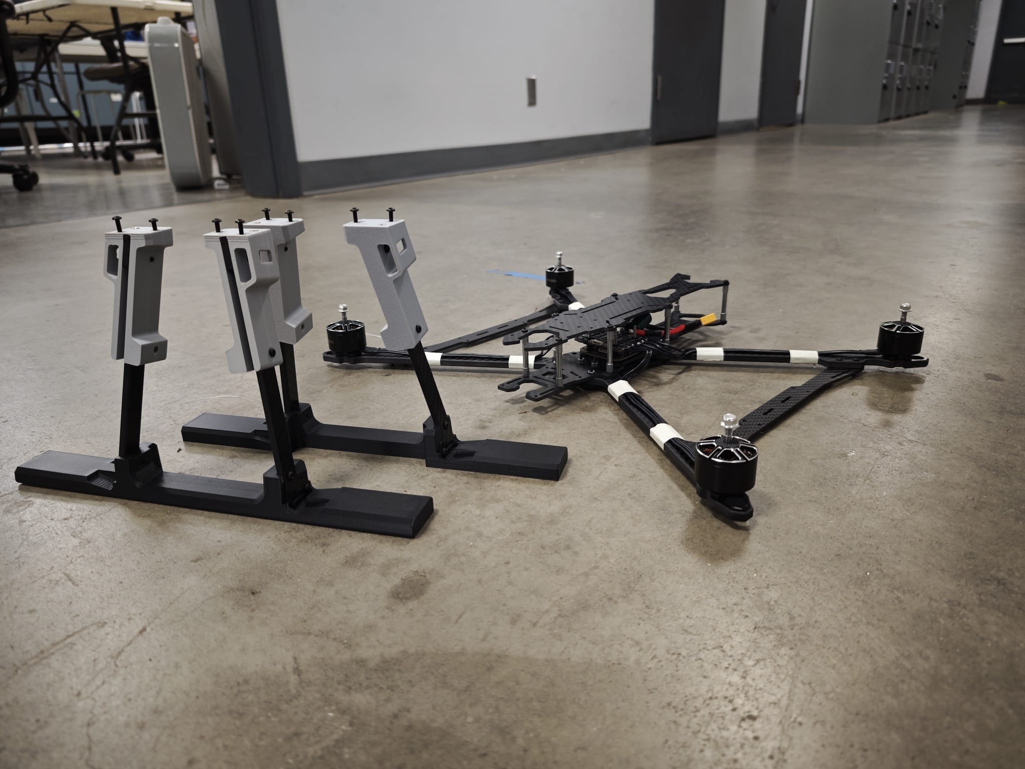
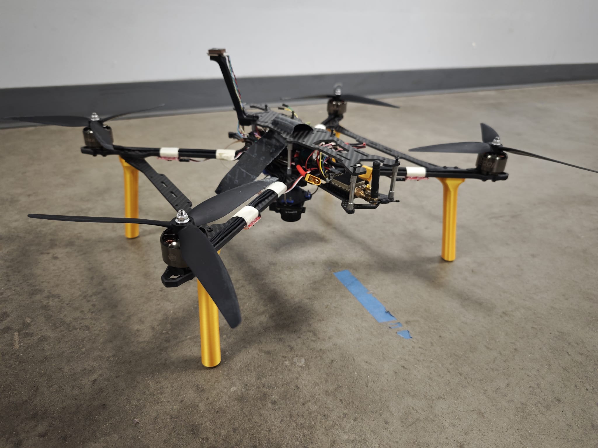
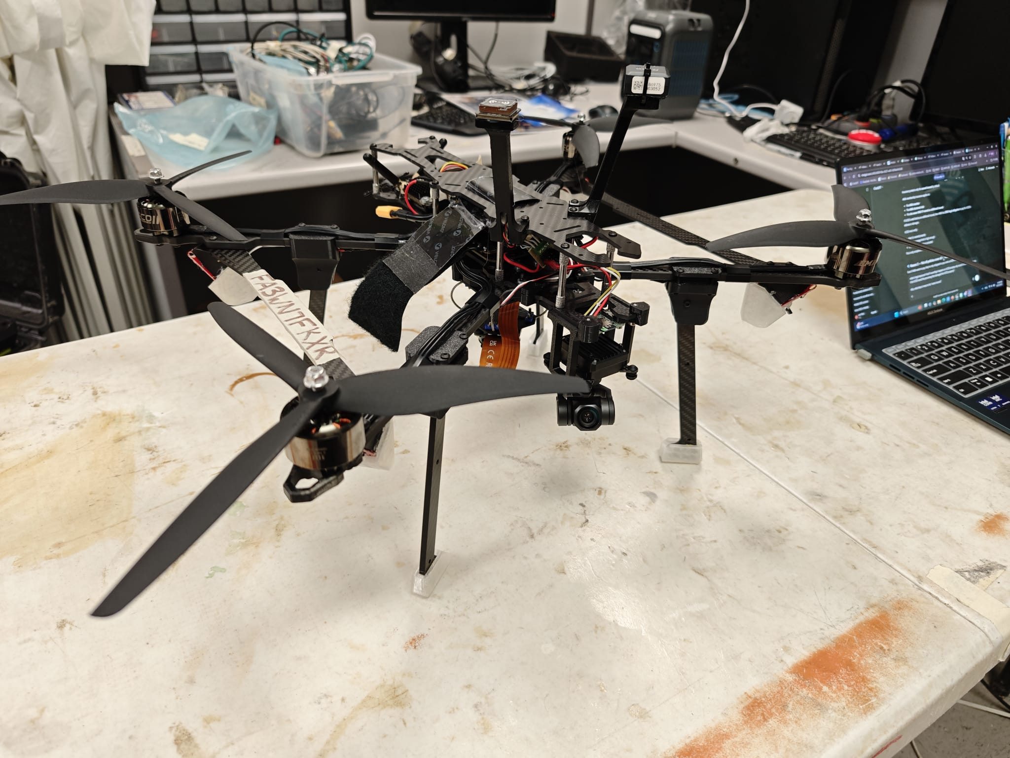
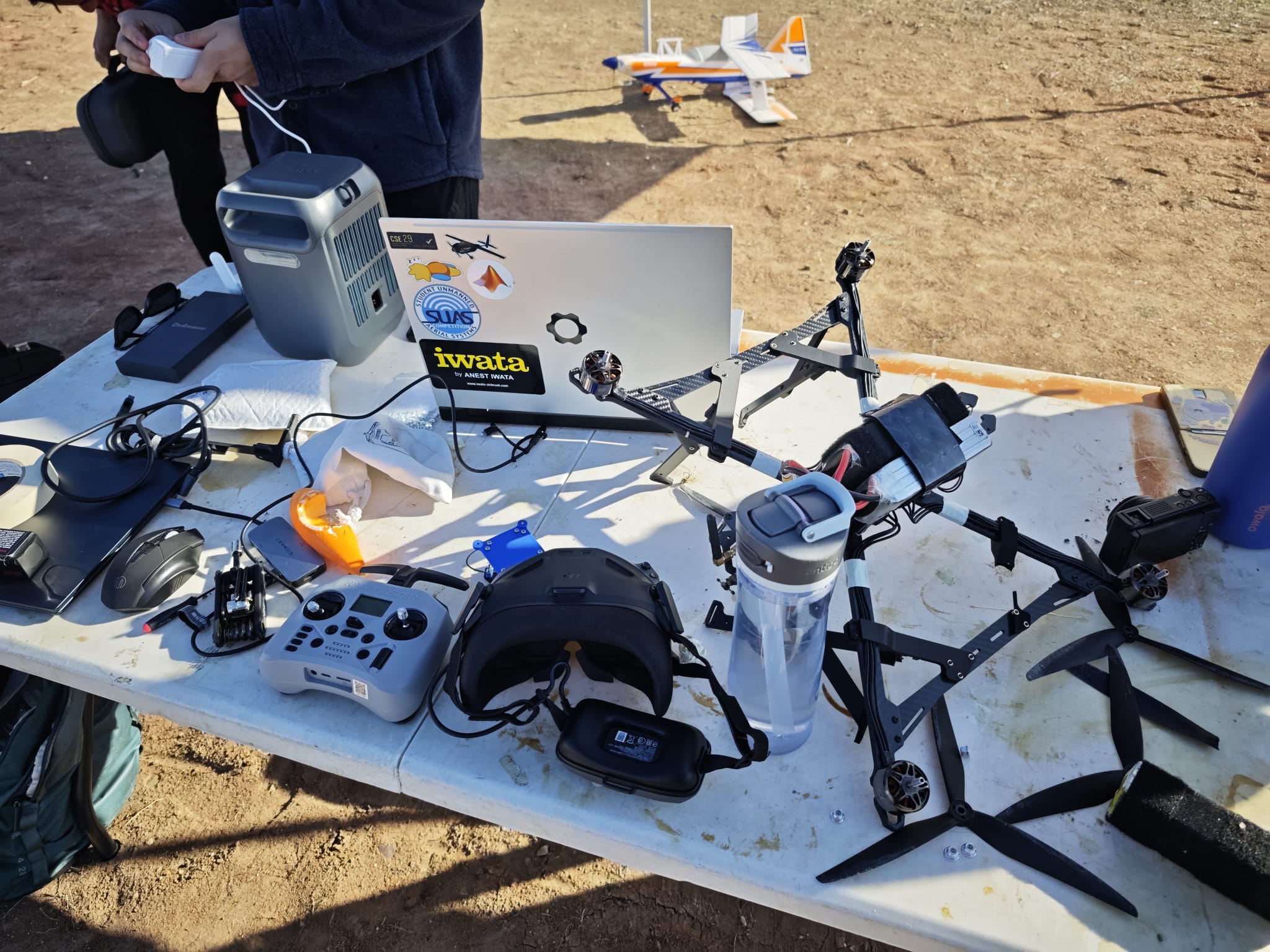
Mechanical assembly
After receiving frame parts, I moved into staged assembly and fit checks before committing to final wiring and flight testing.
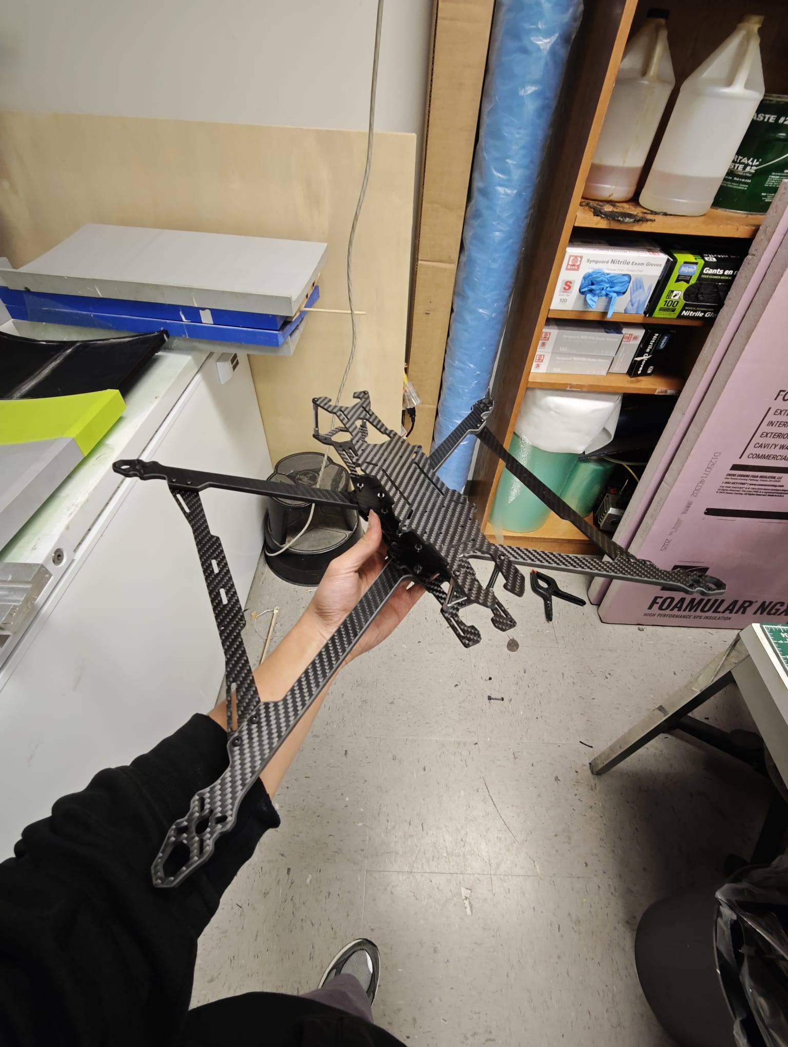
Assembly workflow:
- Dry-fit structural components and verify tolerances.
- Install propulsion and verify clearances.
- Place avionics and adjust component locations to maintain balance and clean cable paths.
- Re-check mounting integrity and center-of-gravity before electrical finalization.
Electrical integration
Electrical integration was built around a robust 8S architecture and reliability under high-current conditions.
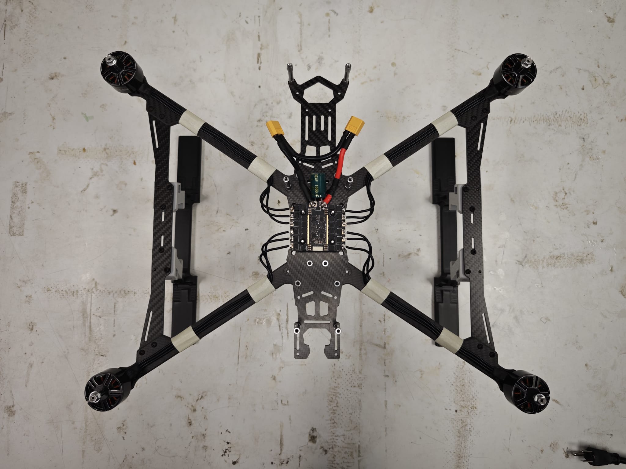
Integration highlights:
- Implemented 2x4S in series (8S) based on mission power requirements.
- Selected motors, ESCs, GPS/radio/sensors, and power electronics as one system rather than isolated parts.
- Completed soldering and harnessing with emphasis on clean routing and stable connections.
- Updated wiring/layout after test observations to reduce interference on sensitive navigation signals.
Flight-test progression
Phase 1: Maiden and baseline stability
Objective: verify safe first flight behavior and capture the first set of tuning issues.
Phase 2: Outdoor tuning and repeatability
Objective: improve consistency in real conditions and tune for stable manual/assisted operation.
Phase 3: Autonomous milestone
Objective: progress from stable flight to guided autonomous takeoff and reliable higher-level flight modes.
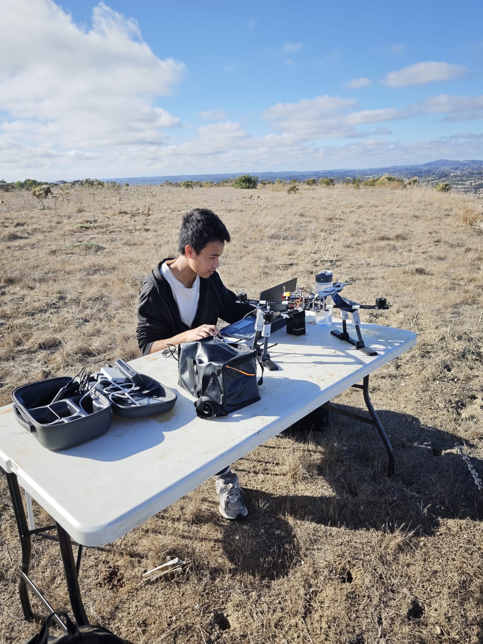
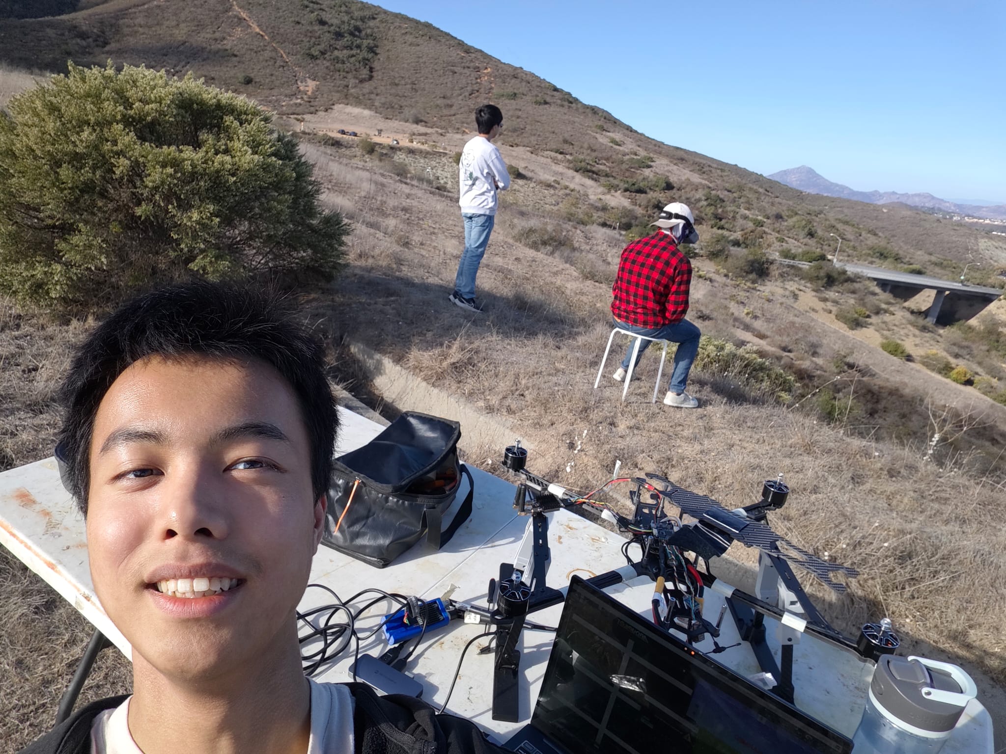
Test campaign progression moved from airworthiness checks to parameter refinement and finally to autonomous demonstrations.
Challenges + Solutions
- Challenge: EKF variance and instability events in early tests
- Cause: electromagnetic interference risk from high-current wiring layout.
- Method: correlated instability events with load conditions and reviewed physical routing.
- Solution: rerouted and isolated sensitive signal paths, improved harness discipline, and adjusted filtering/control parameters.
- Outcome: fewer instability events and stronger confidence entering autonomous modes.
- Challenge: Stable behavior across multiple flight modes
- Cause: initial parameters did not fully match final mass distribution and dynamic response.
- Method: iterative ArduPilot tuning loop after each sortie.
- Solution: systematic PID and parameter refinement using observed flight behavior.
- Outcome: improved loiter stability and more predictable handling.
- Challenge: Mechanical details under real field loads
- Cause: landing-leg and mount details required real-world validation.
- Method: rapid design-build-test iterations.
- Solution: revised geometry and interfaces until strength and practicality were consistent.
- Outcome: more robust landing system and better operational reliability.
- Challenge: Cross-domain integration complexity
- Cause: mechanical, electrical, and autopilot decisions interacted strongly.
- Method: treated each test as a full-system experiment rather than isolated subsystem tuning.
- Solution: coordinated updates across CAD layout, wiring routing, and control configuration.
- Outcome: steady progression from prototype behavior to autonomous demonstration.
Future Improvements
- Add a consolidated public GitHub documentation repository for this platform.
- Integrate higher-level mission automation workflows and repeatable flight-test scripts.
- Extend payload integration and improve EMI hardening for long-duration missions.